Tester Emulation
Emulating automatic test equipment for manufacturing test program development and debugging.
Introduction
Present day test equipment offers flexibility beyond that found only a few years ago. However, there are common resources associated with all test equipment, such as programmable master clock periods, timing generators that shape device inputs and strobes that monitor device outputs. SIMIC's tester-oriented stimulus and strobe definition language emulates the tester environment, allowing test programs to be described concisely and then be debugged during simulation. This has the distinct advantage of minimizing the amount of precious production tester time required for debugging. SIMIC also provides special information about bidirectional pads to insure accurate, non-destructive tests. Finally, since circuit faults are made visible by strobes placed exactly where they will occur on the tester, this mode of simulation allows the most accurate prediction of fault coverage by the SIMIC fault simulator.
Tester Emulation Mode
Defining Master Test Period
Defining a non-zero period automatically causes SIMIC to enter tester emulation mode.
The master period specifies a time interval corresponding to a tester cycle. The start of each interval
begins a new test. The default test period is defined with the PERIOD (PE)
keyword option of the DEFINE (DE) command:
DEFINE PERIOD=<n>
where <n> is the number of time-units in each test period. Defining a period automatically
switches SIMIC into tester emulation mode, and it will remain in tester emulation mode until the master test
period is explicitly removed. This is accomplished by setting the value to 0 with the command:
DEFINE PERIOD=0
The size of the period can be changed during simulation with the APPLY (AP)
PERIOD run command and its BEGIN (BE) option. Its format is:
APPLY PERIOD=<n> BEGIN=<m>
where <n> is the size of the new test period in time-units, and <m>
is the test number at which this period becomes effective. Note that the DEFINE PERIOD command
is functionally equivalent to the APPLY PERIOD command with a BEGIN value of 1.
Defining Drive Values
The drive values, which the tester would apply to primary inputs and primary bidirectional
busses functioning as inputs, are specified by defining patterns. Syntactically, tester
emulation patterns are identical to the simulate-till-stable patterns described in
Input Stimuli. However, when the global period has been set to a non-zero
value (with the DEFINE PERIOD command), SIMIC successively applies the next pattern at the
beginning of the next test period, rather than at the time the circuit state stabilizes.
Defining Timing Generators
Timing generators are essentially timing masks used in conjunction with the current drive value. Two types of masks can be specified: a drive mask, which controls logic levels driven within the test period, and an enable mask, which controls when and whether to tristate drives within the test period. All masks are defined by event times, called marks, that are referenced to the start of the test period.
Drive Mask Formats
One of the following four different drive mask types can be used for each defined timing generator:
1. Non-Return-to-Zero (NRZ)
This mask allows rise and/or fall transitions to be independently skewed from the beginning of the test period.
2. Return-to-Zero (RZ)
This mask is used to define the shape of a positive pulse, generated whenever the drive value is a logical-1 for that period. When the drive is logical-0, the signal remains logical-0 throughout the entire test period (unless the timing generator definition extends over multiple periods).
3. Return-to-One (RO)
This mask is used to define the shape of a negative pulse, generated whenever the drive value is a logical-0 for that period. When the drive is logical-1, the signal remains logical-1 throughout the entire test period (unless the timing generator definition extends over multiple periods).
4. Return-to-Complement (RC)
This mask is commonly used to test setup and hold requirements. It specifies the shape of a negative pulse, when the drive is logical-0, or a positive pulse, when the drive is logical-1, that is preceded and followed by the drive's complement.
Enable Mask Formats
One of the following three enable mask types can be used for each defined timing generator to control when and whether the drive is tristated (Z):
1. No-Envelope (NE)
This mask allows drive-to-tristate and tristate-to-driving transitions to be independently skewed from the beginning of the test period.
2. Return-to-Drive (RD)
This mask is used to shape the tristating window when the driving pattern is a Z.
3. Return-to-Float (RF)
This mask is used to shape the driving window when the driving pattern is not a Z.
Important Note on Drive Retention
SIMIC retains the previous drive value during periods where the drive is specified as Z. This history determines the behavior of the signal when enable mask skews and drive mask skews are not identical. To understand this behavior, view SIMIC as always producing a drive value consistent with the drive format mask and the current (or retained) drive value, which is then connected (or disconnected) as specified by the enable format mask.
Time-Set Definition Syntax
The combination of drive and enable masks constitute a SIMIC time-set. The time-set is
specified with the DEFINE command. One format for this definition is:
DEFINE T<name>.<dformat> = <dmarks>
where <name> is a user-defined name for the time-set, <dformat> is
one of the drive mask types described above, and <dmarks> is a list of marks, or timing
values, whose order and number depends on the <dformat> selected. In this format, no
enable mask was specified.
If not specified, then the enable mask defaults to NE with 0 skewing, with one exception: if
the NRZ driving format mask is used and the rise and fall skews are identical, then the default
is NE with skewing that matches the rise and fall skews.
In order to specify the enable mask the following format is used:
DEFINE T<name>.<dformat>.<eformat> = <dmarks>;<emarks>
Note the addition of <eformat>, which selects one of the enable formats described above,
and <emarks> which is a list of timing values, whose order and number depends on the
selected enable format.
Drive Mask Format Examples
The following diagram illustrates the effects of the four drive mask formats (NRZ, RZ, RO, RC) when applied to the same pattern sequence:
DEFINE PERIOD=1000
DEFINE TNRZ.NRZ = 300
DEFINE TRZ.RZ = 300,700
DEFINE TRO.RO = 300,700
DEFINE TRC.RC = 300,700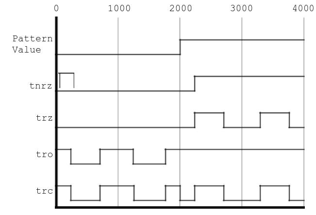
Figure 27: Effect of Sample Drive Format Masks. Note that the NRZ format starts in an unknown (X) state in the first period.
Drive Mask Format Details
| Format | Marks | Description |
|---|---|---|
| NRZ | O, Z | O specifies the time to go to logical-1, when the drive value is logical-1. Z specifies the time to go to logical-0, if the drive value is logical-0. If Z is omitted, then Z is set to the value specified for O. |
| RZ | O, Z1, Z2 | O specifies the time to go to logical-1, when the drive value is logical-1. Z1 specifies the time to go to logical-0, regardless of the drive value. Z2 specifies the time to go to logical-0, only when the time-set is first applied. If omitted, then Z2 is set to 0. In order for the definition to be valid, the magnitudes of the marks must be ordered as follows: Z2 < O < Z1 |
| RO | Z, O1, O2 | Z specifies the time to go to logical-0, when the drive value is logical-0. O1 specifies the time to go to logical-1, regardless of the drive value. O2 specifies the time to go to logical-1, only when the time-set is first applied. If omitted, then O2 is set to 0. In order for the definition to be valid, the magnitudes of the marks must be ordered as follows: O2 < Z < O1 |
| RC | T, C1, C2 | T specifies the time to go to the drive value. C1 specifies the time to return to the complement of the drive value. C2 specifies the time to go to the complement of the drive value, prior to T. If C2 is omitted, then C2 is set to 0. In order for the definition to be valid, the magnitudes of the marks must be ordered as follows: C2 < T < C1 |
Enable Mask Format Examples
The following diagram illustrates the effects of the enable mask formats. The shaded sections indicate disabled (high-impedance/Z) drivers:
DEFINE PERIOD=1000
DEFINE TNE.NRZ.NE = 0,0;500,500
DEFINE TRD.NRZ.RD = 0,0;300,700
DEFINE TRF.NRZ.RF = 0,0;300,700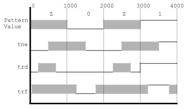
Figure 28: Effect of Sample Enable Format Masks. Shaded sections represent tristated (Z) drivers.
Enable Mask Format Details
| Format | Marks | Description |
|---|---|---|
| NE | F, D | F specifies the time to disable the drive, when the pattern value is 'Z'. D specifies the time to enable the drive, when the pattern value is not a 'Z'. |
| RD | F, D | F specifies the time to disable the drive, when the pattern value is 'Z'. D specifies the time to enable the drive, when the pattern value is 'Z'. In order for the definition to be valid: F < D |
| RF | D, F | D specifies the time to enable the drive, when the pattern value is not 'Z'. F specifies the time to disable the drive, when the pattern value is not 'Z'. In order for the definition to be valid: D < F |
Pulse-Extended Periods
SIMIC does not require mark specifications to be restricted to a single period. A period is called pulse-extended if it continues an active time-set spanning multiple periods. When a new time-set is applied, it is possible for its marks to overlap with the marks of the previous time-set, if the latter's period was pulse-extended. In this situation, SIMIC merges the specifications by following the individual timing mark actions, in the order that they occur. This transient situation ends with the last mark of the previous time-set.
The timing marks Z2 in the RZ drive format and O2 in the RO drive format are only relevant during this transition period, when the new time-set is first applied. They allow injection of a mark forcing the new time-set to become active (e.g., for the RZ format, the signal is forced to 0 at time Z2, regardless of the previous timing-set's definition). If unspecified, Z2 and O2 default to 0, causing a new RZ or RO time-set to become active at the beginning of the period.
Suppressing Timing Marks
Any timing mark can be suppressed by placing an asterisk (*) as a substitute for the value.
For example, to prevent an NRZ timing generator from tristating, even when the pattern value is
'Z', an asterisk should be placed in the 'F' value of the NE enable format specification:
DEFINE TNOFLOAT.NRZ.NE = 500,500;*,0Care should be taken to limit time-set definitions to the capabilities of the target tester.
The number of definable time-sets, active time-sets, number and type of time-set switches, mark suppression, number of periods for which a time-set can be active, and other properties may be restricted by the target tester's capabilities. Therefore, timing-set definitions should be limited to the capabilities of the target tester. For example, while SIMIC supports definition of an unlimited number of time-sets whose active interval can span an arbitrary number of (pulse-extended) test periods, testers contain fixed limits on these resources.
Examples
Example 1: Basic NRZ Timing
>>: DEFINE PERIOD=100
>>: DEFINE TNRZ1.NRZ = 10,10
>>: DEFINE PDATA.8.1.HEX = 00 FF 55 AA
>>: APPLY PATTERN=PDATA TGEN=TNRZ1
This creates an NRZ timing generator where both rise and fall occur at t=10.
Example 2: Clock with RZ (Return-to-Zero)
>>: DEFINE PERIOD=100
>>: DEFINE TCLK.RZ = 10,60,0
>>: DEFINE PCLK.1 = DO 100 (1)
>>: APPLY PATTERN=PCLK TGEN=TCLK LIST=clock
Generates a clock with rising edge at 10, falling edge at 60, starting at 0.
Example 3: Setup/Hold Test with RC
>>: DEFINE PERIOD=100
>>: DEFINE TRC.RC = 50,90,10
>>: DEFINE PTEST.8.1.HEX = 00 11 22 33
>>: APPLY PATTERN=PTEST TGEN=TRC LIST=data[0:7]
Tests setup/hold with data valid from 50 to 90, with setup starting at 10.
Example 4: Bidirectional with Enable Mask
>>: DEFINE PERIOD=100
>>: DEFINE TBIDI.NRZ.NE = 10,10;5,95
>>: DEFINE PIO.8.1.HEX = 00 ZZ FF ZZ AA
>>: APPLY PATTERN=PIO TGEN=TBIDI LIST=bidir[0:7]
Drives 00, tristates, drives FF, tristates, drives AA with proper enable timing.
Assigning Time-Sets to Input and Bidirectional Pads
Once a time-set has been defined as described above, it is attached to primary pads with the
APPLY (AP) TIMING (TI) run command and the
LIST (LI) keyword option. The syntax of this command is:
APPLY TIMING=<time-set> LIST=<signal list>
where <time-set> is the name of a defined time-set (e.g., TNE), and
<signal list> is the list of primary signals to be assigned the specified time-set. If a
primary input/bidirectional pad has not been assigned a timing generator, then the default generator
(TDEFAULT.NRZ.NE=0,0;0,0) will be applied.
Time-sets may be changed at any time during simulation with the APPLY TIMING command with the
BEGIN (BE) keyword option. The form of this command is:
APPLY TIMING=<time-set> LIST=<signal list> BEGIN=<m>where <m> is the test number where this time-set is to be applied.
Defining and Applying Strobes
Strobe Types
SIMIC supports two different types of strobes:
- Point (or Edge) Strobe (SP) - Samples the output at a specific time point
- Window Strobe (SW) - Monitors the output over a time window
In SIMIC, the point strobe can be viewed as a window strobe of zero width. The strobed signal must maintain a constant value within the active window of the strobe, otherwise a strobe error will result. By default, a strobe warning will be generated for each strobe error. This warning may be disabled with the command:
NO WARN STROBE:and re-enabled with the command:
WARN STROBE:In addition, a breakpoint can be set if a strobe error occurs with the command:
BREAK STROBE:This breakpoint can be disabled with the command:
NO BREAK STROBE:Defining Strobes
The format for defining a strobe is:
DEFINE S<name>.<type> = <position>
where <name> is a user-defined name for the strobe, <type> is either
SP (for a point strobe), or SW (for a window strobe), and
<position> is a single value for SP, indicating the time to fire the strobe,
or two values for SW, indicating the time to start and the time to stop the window strobe,
respectively. All times are in time-units, relative to the start of the period.
Example: Window Strobe
The following command defines a window strobe, whose window begins at time 600 and ends at time 700:
DEFINE SDEMO1.SW = 600,700Example: Point Strobe
To define a point strobe at time 800:
DEFINE SDEMO2.SP = 800Assigning Strobes to Outputs and Bidirectional Pads
Strobes are assigned to primary signals in the same fashion as time-sets, with the APPLY TIMING
run command. This format is:
APPLY TIMING=<strobe> LIST=<signal list>
where <strobe> is the name of the strobe (e.g., SDEMO1), and
<signal list> is the list of primary output/bidirectional signals to assign the specified
strobe.
Strobes may be changed at any time during simulation with the APPLY TIMING command with the
BEGIN keyword option. The form of this command is:
APPLY TIMING=<strobe> LIST=<signal list> BEGIN=<m>where <m> is the test number where this strobe is to be applied.
For any output that does not have a strobe assigned, a default point strobe will be placed one time unit prior to the end of the test period.
Expected Results Validation
Introduction
In addition to applying input stimuli, SIMIC provides powerful functionality for specifying expected output values and automatically validating simulation results. This feature works with all three stimulus modes (patterns, waveforms, and timing generators) and is essential for:
Note: Universal Feature
APPLY EXPECTED is available in all simulation modes, not just tester
emulation. For basic usage with patterns and waveforms, see the
Validating Output Results section in Input Stimuli.
This section focuses on the advanced tester emulation capabilities.
- Automated regression testing of circuit designs
- Tester program validation and debugging
- Early detection of functional errors during simulation
- Verification that circuit outputs match design specifications
Defining Expected Results
Expected output values are defined using the same DEFINE command syntax as input patterns.
The only difference is that these patterns will be applied to outputs instead of inputs:
DEFINE P<name>.<width><defaults> = <sequence>Example: Expected Output Pattern
>>: DEFINE PEXPECT.8.1.HEX = 00 FF A5 5A 3C C3
This defines a pattern named PEXPECT with 8 bits, using hexadecimal format, where each
value is maintained for one test period.
Applying Expected Results
Expected results are applied to primary outputs and bidirectional busses using the APPLY
command with the EXPECTED keyword:
APPLY EXPECTED=<pattern> LIST=<signal list> BEGIN=<n>where:
<pattern>is the name of a previously defined pattern (must start withP)<signal list>is a comma-separated list of primary output or bus signals<n>(optional) specifies the test number where checking should begin. If omitted, checking starts immediately.
Example: Complete Expected Results Flow
>>: DEFINE PERIOD=1000
>>: DEFINE PCLK.1 = DO 10 (0 1)
>>: DEFINE PDATA.8.1.HEX = 00 01 02 03 04 05 06 07 08 09
>>: DEFINE POUT_EXPECT.8.1.HEX = 00 02 04 06 08 0A 0C 0E 10 12
>>:
>>: APPLY PATTERN=PCLK LIST=clock
>>: APPLY PATTERN=PDATA LIST=data_in[0:7]
>>: APPLY EXPECTED=POUT_EXPECT LIST=data_out[0:7]
>>:
>>: SIMULATE
In this example, the simulation will automatically compare data_out[0:7] against the
expected values at each test. Any mismatch will generate a warning message.
Automatic Checking Behavior
When expected results are applied, SIMIC automatically validates outputs based on the current simulation mode. The checking mechanism adapts to each mode's characteristics:
- Timing Generators Mode (Tester Emulation): Compares the strobed output value against the expected value at strobe time. This emulates how real test equipment samples outputs at specific timing points.
- Pattern Mode (Simulate-Till-Stable): Compares the stable output value against the expected value when the circuit becomes stable after each pattern. Checking occurs only at stable states, matching the fundamental mode operation.
- Waveform Mode: Compares the current output value against the expected value at each input state change. This provides continuous validation throughout the waveform progression.
- Mismatch Detection: Generates a warning or breakpoint (depending on configuration) whenever actual ≠ expected in any mode
Controlling Mismatch Responses
SIMIC provides fine-grained control over how expected result mismatches are handled using the
WARN and BREAK commands with the EXPECTED keyword:
Enabling Warnings (Default)
By default, mismatches generate warning messages. To explicitly enable warnings for specific outputs:
WARN EXPECTED: LIST=<signal list>Example:
>>: WARN EXPECTED: LIST=data_out[0:7],statusDisabling Warnings
To suppress mismatch warnings for specific outputs:
NO WARN EXPECTED: LIST=<signal list>Example:
>>: NO WARN EXPECTED: LIST=debug_port[0:3]Setting Breakpoints on Mismatches
To halt simulation immediately when a mismatch occurs (useful for interactive debugging):
BREAK EXPECTED: LIST=<signal list>Example:
>>: BREAK EXPECTED: LIST=critical_output,error_flagRemoving Breakpoints
NO BREAK EXPECTED: LIST=<signal list>Mismatch Message Format
When a mismatch is detected, SIMIC generates a message showing:
- The signal name
- The expected value
- The actual (got) value
- The current test number and time
- Message type:
[W]for warning or[B]for breakpoint
Example Mismatch Message
[W] Test 5, Time=4500: Expected result mismatch
    Signal: data_out
    Expected: 0A (hex)
    Got:      08 (hex)
Don't Care Values
Expected patterns support the X symbol to indicate "don't care" values. When the expected
value is X, any actual output value will be considered a match:
>>: DEFINE PEXPECT.8.1.HEX = 00 XX A5 XX FFIn this example, tests 2 and 4 will not generate mismatches regardless of the actual output values.
Use Cases
1. Regression Testing
Create "golden" expected output files and automatically verify that design changes don't break existing functionality:
>>: DEFINE PGOLDEN.32.1.HEX = [... expected values ...]
>>: APPLY EXPECTED=PGOLDEN LIST=cpu_out[0:31]
>>: SIMULATE
>>: # Any mismatches indicate regression
2. Tester Program Validation
Verify that tester patterns will correctly identify good and bad devices:
>>: DEFINE PERIOD=100
>>: DEFINE TDATA.NRZ = 10,10
>>: DEFINE PDATA.16 = ... test vectors ...
>>: DEFINE PEXPECT.16 = ... expected results ...
>>: APPLY PATTERN=PDATA TGEN=TDATA LIST=inputs[0:15]
>>: APPLY EXPECTED=PEXPECT LIST=outputs[0:15]
>>: BREAK EXPECTED: LIST=outputs[0:15]  # Stop on first failure
>>: SIMULATE
3. Interface Verification
Validate that circuit interfaces meet protocol specifications:
>>: # Check handshake protocol
>>: DEFINE PACK_EXPECT.1 = 0 0 0 1 1 1 0
>>: APPLY EXPECTED=PACK_EXPECT LIST=acknowledge
>>: WARN EXPECTED: LIST=acknowledge  # Protocol violation detection
Best Practices
- Start with warnings: Use
WARN EXPECTEDduring initial development to collect all mismatches - Use breakpoints selectively: Set
BREAK EXPECTEDonly on critical signals to avoid stopping on every mismatch - Leverage don't cares: Use
Xvalues for outputs that are timing-dependent or intentionally undefined - Hierarchical checking: Define separate expected patterns for different test phases
and apply them with
BEGINoffsets - Document expectations: Use comments in pattern definitions to explain expected behavior
Test Program Output
Tester Interface File
SIMIC has a special file format for interfacing with testers, called the tester interface
file. This file has the default extension of .tgn, and is created by issuing the
TGEN (TG) command and the FILE (FI) keyword option:
TGEN FILE:or
TGEN FILE=<filename>
prior to simulation, where <filename> is a user-supplied name for the file. This file is
supported for all three stimulus modes.
Since testing involves the final design, the simulation that generates the tester interface file should utilize the most accurate estimates of propagation delays, wiring delays, and timing checks. No degree of unwarranted optimism should be introduced in this simulation. To insure that timing checks and combinational hazard analysis are not defeated or made more lenient, the tester interface file will not be generated if any run command relaxes or restricts X-propagation for timing checks and combinational hazards.
Tester Interface File Contents
The tester interface file will contain the following sections:
1. Time/Date/Version Stamp
This consists of a single line REMARK that contains the time, date and SIMIC version that
created the file.
2. Target Specification
The intended tester is specified with the TGEN command and the TARGET (TA) keyword option:
TGEN TARGET=<name>where <name> is the tester's name. If unspecified, then the name defaults to "???".
3. Channel Section
This section contains, for each primary signal:
- The signal's name
- A character (I, O, or B) specifying that the signal is a primary input, primary output, or primary bus, respectively
- A pin field (always set to unknown (-) by SIMIC)
- A column field locating the position in the output section that contains the signal's value
- A channel field (set unknown by SIMIC)
- A second column field (only for bidirectional signals)
DISCONNECT Option
For bidirectional signals, the second column field specifies the position that contains the value of the
wire-tied signal. The DISCONNECT (DI) option is enabled by default; to disable
this feature, use the run command:
NO TGEN DISCONNECT:and to re-enable it:
TGEN DISCONNECT:or
TGEN DISCONNECT=ALL
The first option will disconnect the primary drive value, except when there is a wire-tie conflict (value
will be X). The second option, ALL, will disconnect the primary drive value for all situations.
4. Run Section
This section begins with an !RUN statement. It only exists if tester emulation mode is in
effect. The contents of this section define:
- The default period (specified by the
DEFINE PERIODcommand) - The correspondence between SIMIC time-units and real-time
- The time-set and strobe definitions (
DEFINE T<name>andDEFINE S<name>) - The time-set and/or strobe to signal assignments (
APPLY TIMINGcommand)
5. Simulation Options Header
This consists of a number of REMARK lines that describe the options selected for simulation.
6. Signal Name Header
This consists of a number of COMMENT lines that contain the names of the signals to be
reported, arranged in columns according to the positional placement of the primary signals in the output
section.
7. Test Output Section
This section begins with an !TGEN statement. It contains a record for each test. For
simulate-till-stable mode, a test output is generated each time the circuit becomes stable; for waveforms, a
test output is generated whenever the circuit becomes stable, or a primary input changes while the circuit is
unstable; and for tester emulation mode, a test output is generated whenever a new period is entered. Each
record contains the word TEST, followed by the current test number, followed by the simulation
test output values, in groups of 5 up to 50 values per line. The "spillover" lines will not contain the
TEST or test number field.
Test Compression
SIMIC automatically compresses identical test output. This can occur for two reasons. First, in simulate
until stable mode, consecutive input patterns are identical. Second, in test emulation mode, consecutive
input patterns are identical, and the strobed results do not change. This can occur in sequential logic,
where several clock cycles are needed to propagate values to the output. These compressed pattern records
will start with the word DO, followed by a number representing the number of times to repeat
this test, followed by an open parenthesis, followed by the test output in the same format as the
TEST records, followed by a close parenthesis.
HIZ Threshold
Values in this table will be only (0, 1, X or Z), since strength is not important to the test equipment.
However, in switch level circuits, there can be very weak "sneak" paths that the tester should treat as high
impedance. The threshold depth at which a path should be considered weak, and a 'Z' should be output to the
tester interface file, is specified with the HIZ option of the TGEN command. For
example:
TGEN HIZ=20000specifies that any paths that have a resultant depth of 20000 or more will be represented as 'Z'.
8. Remark Statements
Besides the above mentioned REMARK output, SIMIC will place any REMARKs in the run
command statements, issued after the TGEN FILE command into the file. This allows designers to
include commentary to the test engineers directly in this tester interface file. Additionally, SIMIC places
SNL remarks read from the backannotation file into this section of the file; thus, net loading information
will be available if timing problems are discovered.
Summary
SIMIC's tester emulation mode provides a comprehensive environment for developing and debugging manufacturing test programs. By emulating automatic test equipment with programmable master clock periods, timing generators that shape device inputs, and strobes that monitor device outputs, SIMIC allows test programs to be thoroughly debugged during simulation before precious production tester time is consumed.
The flexible timing generator system supports NRZ, RZ, RO, and RC drive mask formats, combined with NE, RD, and RF enable mask formats, allowing accurate modeling of real test equipment capabilities. Strobes can be defined as point or window types and applied to outputs to detect timing violations and ensure proper test coverage.
The tester interface file output format provides a standard way to exchange test programs between SIMIC and actual test equipment, making the simulation results directly applicable to manufacturing test development. This integration of simulation and test program development significantly reduces test development time and improves fault coverage prediction accuracy.