Fault Simulation
Simulating faulty circuits to verify test pattern effectiveness.
Fault Simulation is invoked by selecting faults with the FAULT (FA) command. As with fault-free simulation, a subsequently issued SIMULATE command initiates actual simulation. The FAULT command allows you to:
- select the faults to be simulated.
- select the types of reports to be generated by SIMIC.
- control fault simulation parameters.
The SIMIC fault simulator supports incremental test generation and statistical fault sampling.
Since the test stimuli are being verified rather than the design, the fault simulator does not support the design verification capabilities of the fault-free simulator. In particular, the XPROPAGATE and TRACE commands are not supported, timing checks are not performed for functional elements, and the TGEN command is not supported.
Fault Grading
The bottom line in fault simulation is fault grading. The fault grade, or fault coverage, is the percentage of faults detected by the test stimuli:

Fault Selection
In order to perform fault simulation, you must select at least one fault with the FAULT command. Four keywords may be used for fault selection: LIST (LI), INPUTS (IN), OUTPUTS ( OU), and LFILE ( LF). Faults specified with these keywords are subject to name-based filtering (see Fault Filtering).
The LIST Keyword
The LIST (LI) keyword allows selection of specific faults, or all faults. For example:
FAULT LIST=a, b-@-0selects three faults for simulation (a-@-0, a-@-1, and b-@-0) while:
FAULT LIST:selects all faults in the circuit for simulation.
The INPUTS Keyword
The INPUTS keyword (IN) selects all input faults. Its syntax is:
INPUT:The OUTPUTS Keyword
The OUTPUTS keyword (OU) selects all output faults. Its syntax is:
FAULT OUTPUT:
Note: LIST: is the union of all input and output faults. Thus,
FAULT INPUT: OUTPUT:and
FAULT LIST:are equivalent.
The LFILE Keyword
The LFILE (LF) keyword accepts the name of a file that contains the selected fault names. If the complete file name is not specified, the default file extension is .sel. For example:
FAULT LFILE=file1directs SIMIC to read fault names from the file file1.sel.
The second form of the LFILE keyword:
LFILE:directs SIMIC to read the file whose name is the default file name and whose extension is .sel. This file might not reside in the current directory; see Incremental Test Generation.
The files read by the LFILE keyword could have two possible origins:
Generated by a previous SIMIC session. By default, after performing fault simulation, SIMIC writes all undetected and potentially-detected faults to a file whose default extension is .sel. This file is used for incremental test generation (see Incremental Test Generation).
New test stimuli (intended to augment the previously-generated test stimulus set) would be defined for the current simulation session, and the selected faults would be the undetected faults from the previous session. If the new test stimuli are effective, they would be added to the existing tests, and the undetected faults of the current session would be the starting point for the next session.
Created by the user. The format of fault names contained in this file is less stringent than that of the FAULT command’s LIST keyword. Fault names can be separated by spaces, commas, or both. Lines in these files can optionally contain dollar sign ($) continuations, but it is not recommended that too many consecutive lines be continued.
Deselecting Faults
The NO prefix may be used with the FAULT command to remove faults from the selection. For example, the sequence of SIMIC commands:
LIST:
NO FAULT LFILE=file1
NO FAULT LIST=a.();
selects all faults except (a) those contained in file file1.sel, and (b) all input and output faults of parts whose names begin with “a.”.
Output Sensing
In order to determine whether faults have been detected or potentially-detected, the fault-free values of the circuit’s primary busses and outputs are compared to the corresponding faulty values at specific times. The stimulus mode determines when these comparisons are performed:
- For PATTERN mode, outputs are tested when the circuit state has become stable.
- For WAVEFORM mode, outputs are tested either when the circuit state has become stable or when another input event occurs, whichever is earlier.
- For TIMING GENERATOR mode, each output is tested when its output strobe occurs. If the strobe is a window strobe, the output is considered unknown if it is not stable throughout the strobe's width. If no strobe is defined for an output, a default edge strobe is used at the end of the tester period (see Tester Interface for a description of strobes and tester emulation mode).
Example – Fault Simulation Of A Small Combinational Circuit
This section illustrates simulation of a simple combinational circuit, and describes the resulting SIMIC terminal output. The next section describes FAULT command options that enable you to obtain additional information on the selected faults and the fault detection results.
The full-adder circuit of Figure 39 will be used to illustrate the fault simulation run.
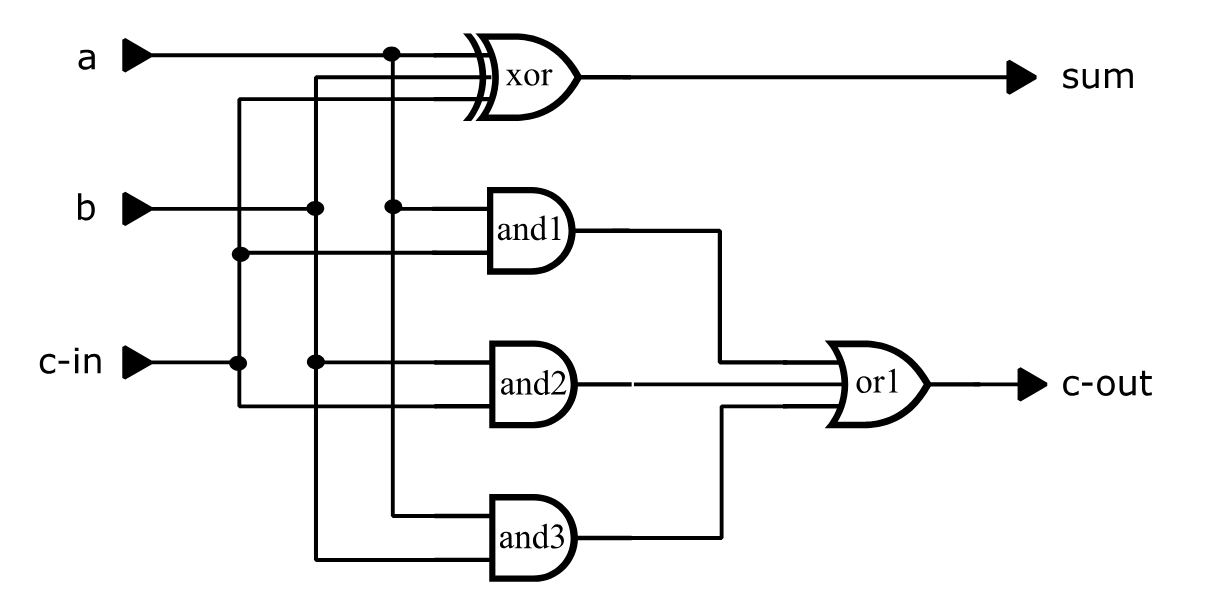
type = full-adder i=a,b,c-in o=sum, c-out
  p=xor t=exor i=a,b,c-in o=sum
  p=and1 t=and i=a,c-in
  p=and2 t=and i=b,c-in
  p=and3 t=and i=a,b
  p=or1 t=or i=and1,and2,and3 o=c-out
Figure 39 Full-Adder Circuit
The following run file selects all faults except input faults at the exclusive-or gate for simulation:
define file=fadder
get type=full-adder
define padder.3 = 000 110 011 111 1X1
apply patterns=padder
fault list:
nofault list=xor;i1,xor;i2,xor;i3
simulate
quit
Note: the order of the inputs is A, B, C-IN, and input B was set to X in the fifth test pattern to cause some faults to be potentially-detected (for example, the fault-free value of C-OUT for this test is logical 1, but if the output of AND gate AND1 were stuck-at-0, then C-OUT would be unknown).
Figure 40 illustrates the terminal output of the resulting SIMIC session. This SIMIC output provides summary information on the total number of faults in the circuit, the number of faults actually simulated, and the fault detection results. This information is provided for both the complete set of faults and the collapsed set; numbers associated with the collapsed set are enclosed in square brackets. Referring to Figure 40:
- SIMIC reports the amount of storage it will use for fault simulation:
INFORMATORY: allocating 300000 words for fault storageThe default storage is 300,000 words (1.2 Mbytes), which should be sufficient for small circuits (< 1,000 parts). Storage Management describes how the amount of fault simulation storage can be changed.
- SIMIC utilizes the real-time clock to create a seed for its random number generator:
Random Number Generator Seed is 534465The random number generator is used to generate fault samples for statistical simulation. The seed is reported so that a run can be exactly repeated, if necessary, for debugging purposes. (See Statistical Fault Simulation.)
- SIMIC provides a summary report on all the faults in the circuit, even
though a subset might actually have been selected for simulation:
Fault Information for Circuit FULL-ADDERIn this example, there are 40 single-stuck faults, and they fall into 25 collapsed groups (numbers in square brackets always refer to the col-lapsed fault set). There are no invisible faults and no faults that are undetectable because of power-rail connections.
- SIMIC provides a summary report on the selected set of faults:
Selected Fault Information = All List-Specified FaultsIf only a subset of all the circuit faults has been selected, SIMIC summarizes the fault counts for the selected faults. In this example, six faults were not selected (the stuck-at-0 and stuck-@-1 at each of the three exclusive-or inputs); thus, SIMIC reports that 34 faults were selected for simulation. These faults fall into 19 collapsed groups. No selected faults are invisible and no selected faults are undetectable because of power-rail connections.
SIMIC then reports the actual number of faults that will be simulated:
Fault Basis For Simulation = 34 [ 19 Collapsed]- If the number of faults to be simulated is too large for the amount of storage available, SIMIC will partition the faults and perform multiple simulation passes. At the end of each pass, SIMIC reports the number of faults that were simulated, detected, or potentially-detected that pass, or that were deferred for the next pass (due to insufficient storage). Cumulative statistics over all passes are also reported. In this
example, all faults were simulated in a single pass:
Fault simulation summary at end of Pass 1:
  Faults simulated this pass = 34 [19 collapsed]
  Faults detected this pass = 24 [12 collapsed]
  Faults potentially detected this pass = 4 [1 collapsed]
  Faults deferred this pass = 0 [0 collapsed]
**Cumulative faults simulated = 34 [19 collapsed]
**Cumulative faults detected = 24 [12 collapsed]
**Cumulative fault coverage = 70.59% [63.16% collapsed]
After all faults have been simulated, SIMIC outputs the box score summarizing the run. The box score entries in this example are:
Faults Simulated – the number of faults simulated. In terms of the complete set of faults, 34 faults were simulated. These faults were represented by 19 collapsed faults.
Actual Detects – the number of faults that were actually detected, i.e., the faulty outputs differed from the fault-free outputs in a known manner. Here, 24 faults in the complete set were detected. These faults were represented by 12 faults in the collapsed set.
Potential Detects – the number of faults that were potentially-detected. There were four faults in the complete set that were potentially detected. These faults were represented by one col-lapsed fault.
Fault Coverage – the resulting fault grade for the run.
In terms of the complete set of faults, the fault coverage could range from 70.59% (24/34), if none of the potentially-detected faults are detected, to 82.35% (28/34) if all of the potentially-detected faults are detected.
In terms of the collapsed set of faults, the fault coverage could range from 63.16% (12/19), if the potentially-detected fault is not detected, to 68.42% (13/19) if this fault is detected.
(Of course, in this example, the potentially-detected faults will not be detected, since the potential detections were caused by an unknown input. For sequential or switch-level circuits, this determination is not obvious.)
Depending on the circuit and simulation options, the box score could contain other entries. These entries are described in Options For Handling Potential Detections and Statistical Fault Simulation.
Main Get Network : FULL-ADDER
Using file: "fadder.net"
GET completed, Circuit totals:  Parts = 5; Signals = 10
   Inputs = 3; Busses = 0; Outputs = 2
Main Get Timing : TYPICAL Circuit Delays
INFORMATORY: allocating 300000 words for fault storage
Random Number Generator Seed is 785514


Fault Information for Circuit FULL-ADDER
        Total Number of Faults =       40 [      25 Collapsed]
     Total Undetectable Faults
           Due To Invisibility =        0
            Due To Power-Rails =        0

    Selected Fault Information = All Input+Output Faults

    Fault Basis For Simulation =       40 [      25 Collapsed]


Fault simulation summary at end of Pass 1:
  Faults simulated this pass = 40 [25 collapsed]
  Faults detected this pass = 30 [18 collapsed]
  Faults potentially detected this pass = 4 [1 collapsed]
  Faults deferred this pass = 0 [0 collapsed]
**Cumulative faults simulated = 40 [25 collapsed]
**Cumulative faults detected = 30 [18 collapsed]
**Cumulative fault coverage = 75% [72% collapsed]

    ***********************************************************************
    ***********************************************************************
    **                                                                   **
    **                 Fault Analysis Report for Design:                 **
    **                             FULL-ADDER                            **
    **                                                                   **
    ** Faults Simulated: All Input + Output Faults                       **
    ** Options: Pdetect= Resolve, Keep Potentially Detected Faults       **
    **          Confidence= 95%                                          **
    **                                                                   **
    **                        |      SELECTED      |     COLLAPSED       **
    **                        |      --------      |     ---------       **
    **  Faults Simulated      |         40         |         25          **
    **  Actual Detects        |         30         |         18          **
    **  Potential Detects     |          4         |          1          **
    **  Fault Coverage        |      75% - 85%     |      72% - 76%      **
    **                                                                   **
    ***********************************************************************
    ***********************************************************************
Figure 40 Terminal Output For Full-Adder Fault Simulation
Fault Simulation Output Files
The three output files are written to the sub-directory specified by the
DIRECTORY keyword.
SIMIC optionally creates three textual fault simulation files:
Undetected and potentially-detected faults for incremental test generation. By default, this file has an extension of .sel.
Fault information based on circuit topology. Reports in this category list the equivalent (collapsed) faults and the suppressed faults, that is, faults that were excluded from consideration because they are inherently undetectable or because of user-specified switch-level options (see Switch-Level And Tristating Components). They are written to the file <default_file>.flt where <default_file> is the default file name.
Fault information based on simulation results. Reports in this category provide fault detection information. They are written to the file <default_file>.rpfwhere <default_file> is the default file name.
Fault Output Subdirectory
Good-logic simulation files are usually written to the current directory. If the fault simulation results are written to the same directory, however, a bookkeeping problem would arise for incremental test generation. Since output file names are keyed to the circuit name, the files created by each iteration would overwrite the files created by the previous iteration, unless (1) these files are renamed or moved before starting the run or (2) a different default file name is used in each run. Either way, a burden would exist to follow some file re-naming convention to avoid losing previous results.
To avoid this problem, the fault simulation output files of each incremental SIMIC run should be written to a dedicated subdirectory. SIMIC supports a subdirectory sequential-naming convention for incremental test generation. This convention can be adapted to utilize other subdirectory naming schemes (see Incremental Test Generation).
The DIRECTORY (DIR) keyword of the FAULT command specifies the directory to which the fault simulation output files should be written. If this keyword is not specified, these files are written to the current directory. The command:
FAULT DIRECTORY=<pathname>directs SIMIC to write the fault simulation outut files to the directory <path-name>.
The command
FAULT DIRECTORY:directs SIMIC to use its default subdirectory naming convention.
The NO prefix forces these files to be written to the current directory:
NO FAULT DIRECTORY:While this is not advisable for iterative simulations, keeping all files in the same directory is more convenient if only one session is required.
Incremental Test Generation File
Unless a path is specified, the incremental test generation file is also written to the sub-directory specified by the DIRECTORY keyword.
The SFILE (SF) keyword of the FAULT command directs SIMIC to generate the file containing undetected and potentially-detected faults for incremental test generation. The command:
FAULT SFILE=<filename>directs SIMIC to write these faults to the designated file. If the specified name is not enclosed by quotation marks, the file’s extension will be .sel. If the specified file name is enclosed in quotation marks, and if this name contains a path, the file will be written to this destination regardless of the selected DIRECTORY option.
The command:
FAULT SFILE:directs SIMIC to write these faults to the file whose name is the default file name and whose extension is .sel. This is the default operation if the SFILE keyword is not specified.
Figure 3.2-3 illustrates the incremental test generation file for the full-adder ( fadder.sel). This file contains the 10 faults that were not detected; the four potentially-detected faults and the six undetected faults (see the box score in Figure 40, page 194).
The NO prefix can be used to inhibit creation of this file:
NO FAULT SFILE: AND1-@-0
AND1;I1-@-1
AND1;I2-@-0
AND1;I2-@-1
AND2;I1-@-1
AND2;I2-@-1
AND3;I1-@-1
AND3;I2-@-1
OR1;I1-@-0Figure 41 Incremental Test Generation File For The Full Adder
Reports On Equivalent And Suppressed Faults
By default, these reports are not generated.
The REPORT (REP) keyword of the FAULT command directs SIMIC to generate reports pertaining to the selected faults. The NO prefix can be used with the REPORT keyword to selectively inhibit reports.
These reports are identical to the corresponding reports generated by the SENSITIZE command, except they contain only selected faults while the reports generated by the SENSITIZE command contain all faults.
As an example, Figure 3.1-4 illustrates the fault equivalence classes for the full-adder circuit.
The command:
FAULT REPORT=EQUIVALENCESdirects SIMIC to report the fault equivalence classes (collapsing), while the command:
FAULT REPORT=SUPPRESSEDdirects SIMIC to report all suppressed faults (see Figure 3.2-6, page 3.2-19).
By default, neither of these reports is generated. This is equivalent to the command:
NO FAULT REPORT=EQUIVALENCES,SUPPRESSEDAny valid prefix of these options containing three or more characters is valid. For example, the following command requests both reports:
REPORT=EQUIV,SUPReports On Detected And Undetected Faults
By default, this file will only contain the box score; all other reports must be explicitly specified.
The REPORT (REP) keyword of the FAULT command directs SIMIC to generate fault detection reports. The NO prefix can be used with the REPORT keyword to selectively inhibit reports.
This file can contain:
The box score.
All detected and potentially detected faults listed alphanumerically.
All detected and potentially detected faults listed by test number.
All undetected and potentially-detected faults.
Figure 42 (page 200) illustrates the .rpf file for the full-adder circuit, which contains all report options. Referring to this figure, the reports utilize the following notational conventions:
All faults prefixed by an asterisk (*) belongs to the collapsed set of faults that was simulated. The remaining faults belong to equivalence classes represented by the collapsed set.
All potentially-detected faults are enclosed in parentheses. Associated
with each potentially-detected fault is a number, enclosed in square braces, that indicates the number of tests in which potential detections occurred, i.e., the fault had at least one unknown output while the cor-responding good output was known.
- For detected faults, the numbers in curly braces are test numbers at which these faults were detected. For potentially-detected faults, the numbers in curly braces are the test numbers at which the first potential detection occurred.
*A-@-0{2}indicates that the fault A-@-0 belongs to the collapsed set and was detected by Test #2. Also, the entry:
(AND1;I2-@-0 [1]){5}indicates that the input fault AND1;I2-@-0 does not belong to the collapsed set, was potentially detected once, and the first (and only) time this fault was potentially-detected was in Test #5.
The command
FAULT REPORT=SCOREdirects SIMIC to write the box score (which is identical to the box score written to the terminal) to the .rpf file. By default, SIMIC does this. To disable writing the box score to this file use the NO prefix:
NO FAULT REPORT=SCOREThe command
FAULT REPORT=BYFAULTdirects SIMIC to generate the list of all detected and potentially-detected faults arranged alphanumerically. Referring to Figure 42 (page 200), this is the section of the report beginning with the heading
**** Detected Faults Listed By Name **** By default, this report is not generated.
The command
FAULT REPORT=BYTEST
directs SIMIC to generate the list of all detected and potentially-detected faults arranged by test number. Potentially-detected faults are listed under the test number at which the first potential detection occurred. Referring to Figure 42, this is the section of the report beginning with the heading
**** Detected Faults Listed By Test **** By default, this report is not generated.
The command
FAULT REPORT=UNDETECTEDdirects SIMIC to generate the list of all undetected and potentially-detected faults arranged alphanumerically. Referring to Figure 42, this is the section of the report beginning with the heading
- Undetected And Potentially Detected Faults****
By default, this report is not generated.
Any valid prefix of these options containing three or more characters is valid. For example, the following commands describe the SIMIC defaults:
FAULT REPORT=SCO
NO FAULT REPORT=BYFAU,BYT,UNDET
Enabling Or Disabling All Reports
All reports on equivalent and suppressed faults, and reports on detected and undetected faults can be simultaneously enabled with the command:
FAULT REPORT:Similarly, these reports can all be simultaneously disabled with the command:
NO FAULT REPORT:Restricting Fault Detection Output To Collapsed Faults
Unless directed otherwise, SIMIC writes selected faults to the .rpf and .sel files. For incremental test generation, however, the collapsed set of undetected and potentially-detected faults is more relevant. While the asterisks designate the collapsed faults in the .rpf file, it could sometimes be more convenient if the .rpf and .sel files contain only collapsed faults. The command
FAULT REPORT=COLLAPSEDdirects SIMIC to write only the collapsed faults to these files.
Changing The Width Of The Report Files
By default, the maximum line width of the .flt and .rpf files is 80 characters. This can be changed with the EXPAND (EX) keyword. The command
FAULT EXPAND:expands the maximum line width of these files to 132 characters.
The NO prefix can be used to restore the default line width:
NO FAULT EXPAND:Remark= 'Fault' Created by SIMIC Version 1.09.01 on Fri Jan 2 15:53:26 2026
***********************************************************************
***********************************************************************
** **
** Fault Analysis Report for Design: **
** FULL-ADDER **
** **
** Faults Simulated: All Input + Output Faults **
** Options: Pdetect= Resolve, Keep Potentially Detected Faults **
** Confidence= 95% **
** **
** | SELECTED | COLLAPSED **
** | -------- | --------- **
** Faults Simulated | 40 | 25 **
** Actual Detects | 30 | 18 **
** Potential Detects | 4 | 1 **
** Fault Coverage | 75% - 85% | 72% - 76% **
** **
***********************************************************************
***********************************************************************
NOTATION:
* A collapsed fault representing all other equivalent faults
during simulation, or a fault that is not equivalent to any
other faults. (Not used with the REPORT=COLLAPSED option.)
! A fault marked as 'detected' because the number of potential
detections reached the potential detection threshold.
(fn[n]) A potentially-detected fault, named 'fn', whose output(s)
differed from the known correct value(s) in 'n' tests
('n' < threshold).
{test} Test at which a fault was detected, or first test at which
a fault was potentially-detected.
**** Detected Faults Listed By Name ****
*A-@-0{2} *A-@-1{1} *(AND1-@-0 [1]){5} AND1-@-1{1}
(AND1;I1-@-0 [1]){5} (AND1;I2-@-0 [1]){5}
*AND2-@-0{3} AND2-@-1{1} AND2;I1-@-0{3} AND2;I2-@-0{3}
*AND3-@-0{2} AND3-@-1{1} AND3;I1-@-0{2} AND3;I2-@-0{2}
*B-@-0{2} *B-@-1{1} *C-IN-@-0{3} *C-IN-@-1{1}
*C-OUT-@-0{2} *C-OUT-@-1{1} (OR1;I1-@-0 [1]){5} OR1;I1-@-1{1}
OR1;I2-@-0{3} OR1;I2-@-1{1} OR1;I3-@-0{2} OR1;I3-@-1{1}
*SUM-@-0{4} *SUM-@-1{1} *XOR;I1-@-0{2} *XOR;I1-@-1{1}
*XOR;I2-@-0{2} *XOR;I2-@-1{1} *XOR;I3-@-0{3} *XOR;I3-@-1{1}
**** Detected Faults Listed By Test ****
Faults Detected By Test 1
*A-@-1 AND1-@-1 AND2-@-1 AND3-@-1
*B-@-1 *C-IN-@-1 *C-OUT-@-1 OR1;I1-@-1
OR1;I2-@-1 OR1;I3-@-1 *SUM-@-1 *XOR;I1-@-1
*XOR;I2-@-1 *XOR;I3-@-1
Faults Detected By Test 2
*A-@-0 *AND3-@-0 AND3;I1-@-0 AND3;I2-@-0
*B-@-0 *C-OUT-@-0 OR1;I3-@-0 *XOR;I1-@-0
*XOR;I2-@-0
Faults Detected By Test 3
*AND2-@-0 AND2;I1-@-0 AND2;I2-@-0 *C-IN-@-0
OR1;I2-@-0 *XOR;I3-@-0
Faults Detected By Test 4
*SUM-@-0
Faults Detected By Test 5
*(AND1-@-0 [1]) (AND1;I1-@-0 [1]) (AND1;I2-@-0 [1]) (OR1;I1-@-0 [1])
**** Undetected And Potentially Detected Faults ****
*(AND1-@-0 [1]) (AND1;I1-@-0 [1]) *AND1;I1-@-1 (AND1;I2-@-0 [1])
*AND1;I2-@-1 *AND2;I1-@-1 *AND2;I2-@-1 *AND3;I1-@-1
*AND3;I2-@-1 (OR1;I1-@-0 [1])Figure 42 Fault Detection Report for the Full-Adder Circuit (fadder.rpf)
Incremental Test Generation
The process of incremental test generation can be summarized as follows:
- Each iteration starts with a set of undetected faults. Initially, this set would contain all selected faults in the circuit.
- Test stimuli are generated for the undetected faults, and fault simulation is performed using only these faults. The undetected faults resulting from this simulation are the starting point for the next iteration.
As was discussed in Fault Output Subdirectory, no simulation should overwrite the results of previous simulations. Also, the run file modifications required between iterations should be minimal to reduce the possibility of error.
Auto-Numbered Fault Simulation Directories
The 2-digit auto-numbering convention supports 100 iterations.
SIMIC supports a directory auto-numbering system for incremental test generation. You can, however, specify directory options and path names to implement another methodology, if desired.
In the auto-numbering convention, directory names contain a 2-digit suffix that represents an iteration index. The supported index range is from 00 through 99, inclusive. Each directory is dedicated to a single iteration; the directory contains all fault-related SIMIC output files that are specific to the iteration's test stimuli. These files include the incremental test generation file, the fault simulation report files, and, optionally, sensitization analysis results for the stimuli (see Using Sensitization Information). (Each directory might also contain the test stimuli used in that iteration.)
For example, if you specify that iterations produce auto-numbered subdirectories of the current directory named mydir, then successive iterations will create subdirectories mydir00, mydir01, mydir02, etc. Subdirectory mydir00 will contain all fault simulation files generated by the initial simulation, subdirectory mydir01 will contain all fault simulation files generated by the first iteration (second simulation), subdirectory mydir02 will contain all fault simulation files generated by the second iteration, etc.
The directory that fault simulation results are written to in the current iteration is called the output fault directory. The directory that fault simulation results were written to in the previous iteration is called the previous fault directory. The index of the previous fault directory is always one less than the index of the output fault directory. For example, if the output fault directory is mydir03, the previous fault directory would be mydir02.
If auto-numbered fault directories are being used (see below), and if the LFILE specification does not contain a path name, the previous fault directory is searched for the incremental test generation file of the previous iteration. If the previous fault directory does not exist, or if this file cannot be
The current directory is searched for the incremental test generation file if this file cannot be found in the previous fault directory.
found in the previous fault directory, the current directory is searched as an alternative path. For example, suppose that the output fault directory is mydir03. Then the command:
FAULT LFILE: SFILE:would cause SIMIC to search the directory mydir02 for a file whose name is the default file name and whose extension is .sel (LFILE:). If this file is not found, the current directory would then be searched for this file. The incremental test generation file for the current run will also have the default file name and the default extension .sel (SFILE:), and this file will be written to directory mydir03.
The output fault directory could either be created by SIMIC or by the user, depending on the selected directory strategy.
Default Subdirectory Operation
If the default form of the DIRECTORY keyword is specified:
FAULT DIRECTORY:then SIMIC will always create a new, specially-named output fault directory, which will be a subdirectory of the current directory. The subdirectory name has the form:
<default_file>.fnn
where nn is a 2-digit decimal number (index) from 00 to 99. If no subdirectory with this type of name exists, as would be the case the first time fault simulation is performed for a circuit, SIMIC writes the fault simulation output files to the subdirectory <default_file>.f00. If subdirectories with this type of name already exist, the subdirectory with the highest 2-digit index will become the previous fault directory. SIMIC will then create the output fault directory as a new subdirectory whose 2-digit index is 1 greater than that of the previous fault directory.
For example, the sequence of subdirectories:
fadder.f00, fadder.f01, …
would be created for the full-adder circuit. Suppose that the last subdirectory created was fadder.f04. On the next iteration, subdirectory fadder.f05 would be created as the output fault directory, and subdirectory fadder.f04 would be used as the previous fault directory.
Note: if more than 100 iterations are required to generate test stimuli, alternative naming will be required; if <default_file>.99 exists, SIMIC will write the fault simulation output files to the current directory.
Default Operation With User-Defined Directory Names
If the path name specified with the DIRECTORY keyword ends in "__" (two underscore characters), SIMIC will also utilize the default subdirectory conventions, except with the user-defined prefix. For example, the command
FAULT DIRECTORY=mydir__would cause the sequence of subdirectories mydir00, mydir01, … to be created. Note that the default subdirectory naming convention is equivalent to:
FAULT DIRECTORY=<default_file>.f__Since the DIRECTORY keyword accepts quoted strings, the specified directory path need not be a subdirectory of the current directory.
Using The Last Directory As The Output Fault Directory
If the path name specified with the DIRECTORY keyword ends with a single underscore, SIMIC will not create a new subdirectory; the previously-existing subdirectory with the highest 2-digit index will be used as the output fault directory. If the next-previous sequential subdirectory exists, it will be the previous output directory.
For example, if the command:
FAULT DIRECTORY=mydir_is specified, and if the only the subdirectories mydir00, mydir01, and mydir02 exist, then the output fault directory will be mydir02 and the previous fault directory will be mydir01.
Note:
The previous fault directory would be undefined if the previous sequential subdirectory does not exist (e.g., in the above example, if only mydir00 exists, or if only mydir00 and mydir02 exist).
If no directories with the specified path name prefix exist, the output fault directory will be the current directory, and the previous fault directory would be undefined.
Operation For Other User-Specified Directory Names
If the path name specified with the DIRECTORY keyword does not end with an underscore (single or double), SIMIC will write the fault simulation output files to this directory. If the directory does not exist, SIMIC will create it.
Additionally, if the last two characters of the path name are numeric digits from 01 through 99, and if the previous sequential subdirectory exists, the latter will be the previous output directory. Otherwise the previous output directory will be undefined.
For example, the command:
FAULT DIR=mydir07specifies the output fault directory as mydir07. If the directory mydir06 exists, is will be the previous output directory.
Suppressed Undetectable Faults
A fault can be undetectable for a number of reasons:
- The fault does not affect any visible (primary) output. This occurs when there is no topological path from the fault site to any visible output (e.g., unused elements or outputs of standard cells).
- The fault site cannot be driven to the complement of the stuck-at value. This usually occurs when a signal is always driven to the same constant value or is blocked by power-rail connections.
- The fault cannot be sensitized because it is associated with redundant logic.
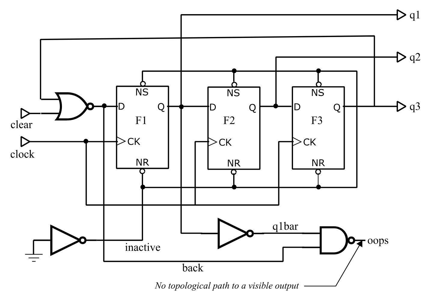
!f p= t= i= o= ochange=
t=jctr i=clear, clock o=q1,q2,q3
   f1       dcf          inactive,inactive,clock,back    q1    1
   f2       dcf          inactive,inactive,clock,q1      q2    1
   f3       dcf          inactive,inactive,clock,q2      q3    1
   inactive inv          zero
   back     nor          q3,clear                        back  1
   q1bar    inv          q1
   oops     nand         q1bar,back
Figure 43 Modified Johnson Counter
SIMIC always removes faults in the first two categories from consideration, since they would otherwise reduce the maximum possible fault coverage.
Consider, for example, the modified Johnson Counter illustrated in
:
There is no path from signal OOPS to any visible output. Thus, faults at the pins of the AND gate generating this signal can never be detected. Also, since signal Q1BAR only drives this AND gate, the same can be said for faults at the inverter generating Q1BAR.
Signal INACTIVE is always logical 1 to disable the asynchronous Set and Reset inputs of the flip-flops. Since this signal never becomes logical 0, it is impossible to detect a stuck-at-1 fault on this signal or on any of the asynchronous flip-flop pins. (If any of these faults occurred, the circuit would still operate correctly.)
In total, there are 10 invisible faults and 8 faults that are undetectable due to power-rail connections, as shown in Figure 44. This report was generated with the command
REPORT=SUPPRESSEDSince the total number of single-stuck faults for this circuit is 54 (see Section 3.2.8), the maximum possible fault coverage would only be (54 - 18)/ 54 = 66.67% if these undetectable faults were not suppressed.
SIMIC always reports the number of suppressed undetectable faults in each category in the terminal output’s fault summary section. This section begins with the heading:
Fault Information for Circuit <circuit_name>
Figure 44 Suppressed Fault Report for Modified Johnson Counter
Options For Handling Potential Detections
RESOLVE is the default strategy if PDETECT is not specified.
Potential detections typically occur in sequential circuits, where state variables may not be initialized in the presence of certain faults. Latch and flip-flop states remain unknown (X) in these faulty circuits, while they are properly initialized in the fault-free circuit. Faults can also introduce timing problems and wire-tie conflicts that cause signal values to become unknown. As a result, primary outputs of the faulty circuit are either unknown while the corresponding good outputs are known, or are identical to the fault-free outputs.
The unknown faulty circuit states arise because the simulator cannot determinate them. The actual circuit, of course, will not contain X values in the presence of the faults. At the tester, it will power up in some state, where each signal level is either logical 0 or logical 1, and respond to the test stimuli by executing transitions to other states whose signal levels are either logical 0 or logical 1. Thus, it is possible that some potentially detected faults may actually be detected at the tester, while others may not (this is the reason “potential detections” are so-named)1.
Since the operation of the actual circuit is indeterminate during simulation, how should potential detections be handled? The answer depends on the particular test specifications for each design. SIMIC supports three options:
NONE – Do not infer whether potentially-detected faults might actually be detected at the tester.
SOFT – Classify faults that have been potentially-detected a user-specified number of times (tests) as “detected”. These are called soft detections, in contrast with hard, or actual, detections.
RESOLVE – Use the resolution algorithm built into SIMIC to handle potentially-detected faults.
The third option is recommended, since it produces the most realistic detection estimates. It is utilized by default, if no other strategy is specified.
The PDETECT (PD) keyword of the FAULT command specifies how potential detections should be handled. The command format is:
FAULT PDETECT=<strategy>,<drop_threshold>
where:
<strategy> is any prefix NONE, SOFT, or RESOLVE.
<drop_threshold> is an integer that specifies the number of times that potential detections should be counted for each fault before it is dropped from simulation.
- For some potentially-detected faults, knowledge of the initial state is still not sufficient to determine operation at the tester. These are faults that introduce timing problems, cause wire-tie contention, introduce quasi-stable operation or oscillation, etc.
The <drop_threshold> parameter serves the purpose of reducing fault simulation time for NONE and RESOLVE, and is optional for these selections. If this parameter is omitted, potentially-detected faults are never dropped. For example:
FAULT PDETECT=NONE,100specifies that detection should not be inferred from potential detection and that faults should be dropped from simulation after they are potentially-detected 100 times.
The command:
FAULT PDETECT=RESOLVEspecifies that the SIMIC potential detection resolution algorithm should be used, and that potentially-detected faults should never be dropped. This is the default operation if the PDETECT keyword is not specified.
Note: the PDETECT parameters are not “sticky”; the <drop_threshold> parameter specified in one FAULT command does not carry over if the PDETECT keyword is re-specified with no <drop_threshold> parameter in a subsequent FAULT command.
The <drop_threshold> parameter specifies the soft detection threshold for
SOFT, and is therefore required for this option. For example:
FAULT PDETECT=SOFT,150specifies that any fault that has been potentially-detected 150 times should be classified as a soft detection, and dropped from simulation.
The selected PDETECT option is always reported in the box score.
The remainder of this section illustrates simulation of the modified Johnson counter with each of the three potential detection options. Except for the selected PDETECT option, all three simulations use the run commands shown in Figure 45. Also, the terminal output of all three simulations contain the same Fault Information section and good-logic simulation results shown in Figure 46. The fault simulation results are different, however.
define file=jctr
get type=jctr
print list=clear, clock,*,back*q1,q2,q3
define pclear.1 = 1 1 1 1 1 1 0 0 0 0 0 0 0 0 0 0 0 0 1
define pclock.1 = do 10 (0 1 )
apply pattern=pclear list=clear
apply pattern=pclock list=clock
fault pdetect=<pdetect_option> ø simulations differ here
fault list: report=bytest,undetected
simulate
quit
Figure 45 Run Commands for Modified Johnson Counter Simulations
Fault Information for Circuit JCTR
        Total Number of Faults =       54 [      28 Collapsed]
     Total Undetectable Faults
           Due To Invisibility =       10 [       1 Collapsed]
            Due To Power-Rails =        8 [       1 Collapsed]

    Selected Fault Information = All Input+Output Faults

    Fault Basis For Simulation =       36 [      26 Collapsed]

Remark= Options: (Fault Simulation)
Remark=   Pattern Stimuli, Near Filter, Spike Filter
Remark=   Stable After Decay, Dynamic Delay, No Charge Sharing

C=                 CC B QQQ
C=                 LL A 123
C=                 EO C
C=                 AC K
C=                 RK

        2 T     1: 10 0 XXX
        1 T     2: 11 0 0XX
        1 T     3: 10 0 0XX
        1 T     4: 11 0 00X
        1 T     5: 10 0 00X
        1 T     6: 11 0 000
        2 T     7: 00 1 000
        1 T     8: 01 1 100
        1 T     9: 00 1 100
        1 T    10: 01 1 110
        1 T    11: 00 1 110
        2 T    12: 01 0 111
        1 T    13: 00 0 111
        1 T    14: 01 0 011
        1 T    15: 00 0 011
        1 T    16: 01 0 001
        1 T    17: 00 0 001
        2 T    18: 01 1 000
        2 T    19: 10 0 000
        0 T    20: 11 0 000
Figure 46 Common Terminal Output Of Modified Johnson Counter Simulations
Note: the DCF built-in primitive is a positive-edge triggered D flip-flop with active-low Set (NS) and Reset (NR) inputs.
Example – Handling Potential Detections With NONE
Figure 47 illustrates the simulation results if the command:
fault pdetect=none
were used in the run file of Figure 45. (For brevity, blank lines and the SIMIC-generated remarks were removed.) No attempt is made to infer detection from potential detections. Ten faults (9 collapsed) were potentially detected; for example, CLEAR-@-0 was potentially detected in 19 tests, and F2;C-@-0 (the Clock pin of flip-flop F2) was potentially detected in 17 tests. Two faults, F3;C-@-0 and F3;C-@-1, were potentially detected 15 times. No faults remained undetected.
Example – Handling Potential Detections With SOFT
Figure 48 illustrates the simulation results if the command:
pdetect=soft,17were used in the run file of Figure 45. (For brevity, blank lines were removed.) Therefore, all faults that were potentially-detected in at least 17 tests will be classified as soft detections. Only two of the ten potentially-detected faults, F3;C-@-0 and F3;C-@-1, fall short of this threshold; thus, in Figure 48, only these two faults remain in the “Undetected and Potentially Detected” category.
The eight potentially-detected faults that have been classified as soft detections are distinguished by a leading exclamation mark (!) in the .rpf file. Also, these faults are associated with the test in which the threshold was attained rather than with the test in which the first potential detection occurred. For example, the fault CLEAR-@-0 was first potentially-detected in Test #2 (Figure 48Figure 47), and the 17-th potential detection occurred in Test #18. Thus, the entry !CLEAR-@-0 is under Test #18 in Figure 48.
Referring to Figure 47, the NOTATION explanation for leading exclamation marks in the .rpf file contains the soft detection threshold (17):
- A fault marked as ‘detected’ because the number of potential detections reached the potential detection threshold (17).
Note: had the soft detection threshold been set at 15 (or less), all faults would have been classified as detected.
Example – Handling Potential Detections With RESOLVE
Figure Figure 50 illustrates the simulation results if the command:
fault pdetect=resolve
were used in the run file of Figure 45. (For brevity, blank lines and the SIMIC-generated remarks were removed.) All faults were found to be detected.
Remark= 'Fault' Created by SIMIC Version 1.09.01 on Fri Jan  2 15:59:44 2026

    ***********************************************************************
    ***********************************************************************
    **                                                                   **
    **                 Fault Analysis Report for Design:                 **
    **                                JCTR                               **
    **                                                                   **
    ** Faults Simulated: All Input + Output Faults                       **
    ** Options: Pdetect= None, Keep Potentially Detected Faults          **
    **          Confidence= 95%                                          **
    **                                                                   **
    **                        |      SELECTED      |     COLLAPSED       **
    **                        |      --------      |     ---------       **
    **  Faults Simulated      |         36         |         26          **
    **  Actual Detects        |         26         |         17          **
    **  Potential Detects     |         10         |          9          **
    **  Fault Coverage        |    72.22% - 100%   |    65.38% - 100%    **
    **                                                                   **
    ***********************************************************************
    ***********************************************************************

NOTATION:

	*	A collapsed fault representing all other equivalent faults
		during simulation, or a fault that is not equivalent to any
		other faults. (Not used with the REPORT=COLLAPSED option.)

	!	A fault marked as 'detected' because the number of potential
		detections reached the potential detection threshold.

	(fn[n])	A potentially-detected fault, named 'fn', whose output(s)
		differed from the known correct value(s) in 'n' tests
		('n' < threshold).

	{test}	Test at which a fault was detected, or first test at which
		a fault was potentially-detected.

                    **** Detected Faults Listed By Test ****

Faults Detected By Test 2
*BACK-@-1           (BACK;I2-@-0 [19])  *(CLEAR-@-0 [19])   *(CLOCK-@-0 [19])
*(CLOCK-@-1 [19])   *(F1;C-@-0 [19])    *(F1;C-@-1 [19])    F1;D-@-1
F1;NS-@-0           *INACTIVE-@-0       INACTIVE;I1-@-1     *Q1-@-1

Faults Detected By Test 4
*(F2;C-@-0 [17])    *(F2;C-@-1 [17])    *F2;D-@-1           F2;NS-@-0
*Q2-@-1

Faults Detected By Test 6
*(F3;C-@-0 [15])    *(F3;C-@-1 [15])    *F3;D-@-1           F3;NS-@-0
*Q3-@-1

Faults Detected By Test 8
*BACK-@-0           BACK;I1-@-1         BACK;I2-@-1         CLEAR-@-1
F1;D-@-0            *F1;NR-@-0          *Q1-@-0

Faults Detected By Test 10
*F2;D-@-0           *F2;NR-@-0          *Q2-@-0

Faults Detected By Test 12
*F3;D-@-0           *F3;NR-@-0          *Q3-@-0

Faults Detected By Test 14
*BACK;I1-@-0

              **** Undetected And Potentially Detected Faults ****
(BACK;I2-@-0 [19])  *(CLEAR-@-0 [19])   *(CLOCK-@-0 [19])   *(CLOCK-@-1 [19])
*(F1;C-@-0 [19])    *(F1;C-@-1 [19])    *(F2;C-@-0 [17])    *(F2;C-@-1 [17])
*(F3;C-@-0 [15])    *(F3;C-@-1 [15])
Figure 47 Modified Johnson Counter Report File for PDETECT=NONE
Remark= ‘Fault’ Created by SIMIC Version 1.01.00 on Mon Aug 23 21:35:51 1993
Remark= 'Fault' Created by SIMIC Version 1.09.01 on Fri Jan  2 16:08:23 2026

    ***********************************************************************
    ***********************************************************************
    **                                                                   **
    **                 Fault Analysis Report for Design:                 **
    **                                JCTR                               **
    **                                                                   **
    ** Faults Simulated: All Input + Output Faults                       **
    ** Options: Pdetect= Drop, Drop Faults after 17 Potential Detections **
    **          Confidence= 95%                                          **
    **                                                                   **
    **                        |      SELECTED      |     COLLAPSED       **
    **                        |      --------      |     ---------       **
    **  Faults Simulated      |         36         |         26          **
    **  Actual Detects        |         26         |         17          **
    **  Soft Detects          |          8         |          7          **
    **  Potential Detects     |          2         |          2          **
    **  Fault Coverage        |    94.44% - 100%   |    92.31% - 100%    **
    **                                                                   **
    ***********************************************************************
    ***********************************************************************

NOTATION:

	*	A collapsed fault representing all other equivalent faults
		during simulation, or a fault that is not equivalent to any
		other faults. (Not used with the REPORT=COLLAPSED option.)

	!	A fault marked as 'detected' because the number of potential
		detections reached the potential detection threshold (17).

	(fn[n])	A potentially-detected fault, named 'fn', whose output(s)
		differed from the known correct value(s) in 'n' tests
		('n' < threshold).

	{test}	Test at which a fault was detected, or first test at which
		a fault was potentially-detected.

                    **** Detected Faults Listed By Test ****

Faults Detected By Test 2
*BACK-@-1           F1;D-@-1            F1;NS-@-0           *INACTIVE-@-0
INACTIVE;I1-@-1     *Q1-@-1

Faults Detected By Test 4
*F2;D-@-1           F2;NS-@-0           *Q2-@-1

Faults Detected By Test 6
*(F3;C-@-0 [15])    *(F3;C-@-1 [15])    *F3;D-@-1           F3;NS-@-0
*Q3-@-1

Faults Detected By Test 8
*BACK-@-0           BACK;I1-@-1         BACK;I2-@-1         CLEAR-@-1
F1;D-@-0            *F1;NR-@-0          *Q1-@-0

Faults Detected By Test 10
*F2;D-@-0           *F2;NR-@-0          *Q2-@-0

Faults Detected By Test 12
*F3;D-@-0           *F3;NR-@-0          *Q3-@-0

Faults Detected By Test 14
*BACK;I1-@-0

Faults Detected By Test 18
!BACK;I2-@-0        *!CLEAR-@-0         *!CLOCK-@-0         *!CLOCK-@-1
*!F1;C-@-0          *!F1;C-@-1

Faults Detected By Test 20
*!F2;C-@-0          *!F2;C-@-1

              **** Undetected And Potentially Detected Faults ****

*(F3;C-@-0 [15])    *(F3;C-@-1 [15])
Figure 48 Modified Johnson Counter Report File for PDETECT=SOFT
The RESOLVE option generally provides realistic estimates of which potentially-detected faults may actually be detected at the tester, and when these faults may be detected.
For example, in Figure 50, the faults CLOCK-@-0 and CLOCK-@-1 were classified as detected in Test #8, which happens to be the latest test in which these faults would be detected. Referring to the fault-free response in Figure 46 (page 209), signal Q1 becomes logical 0 in Test #2. If this flip-flop powered up in the Set state (Q1 = logical 1), the clock faults would be detected then. However, if it powered up in the Reset state (Q1 = logical 0), the value of Q1 in Test #2 would be correct, and the clock faults would only be detected when Q1 will change state again, which is in Test #8.
Similarly, the fault CLEAR-@-0 was classified as detected in Test #20. This fault would be detected anywhere between Test #2 and Test #6 for all initial states except (Q1,Q2,Q3) = (0,1,1). If the counter did power up in this state, the counter outputs in the faulty circuit would be correct through Test #19. In Test #20, however, the CLEAR input would hold Q1 at logical 0 in the fault-free circuit, while Q1 in the faulty circuit would become logical 1 (since the D input of this flip-flop would be the inverted value of Q3). Thus, Test #20 is the latest test in which the fault CLEAR-@-0 would be detected.
Figure 50 Modified Johnson Counter Report File For PDETECT=RESOLVE
Fault Filtering
Name-based filtering is a method of systematically excluding fault sites. Thus, it does not operate on LIST specifications when the NO command prefix is used.
By default, faults are filtered at parts and signals whose names contain ‘?’.
While the LIST and LFILE keywords provide flexibility in selecting and excluding faults from simulation, using these keywords to specify a large number of faults can be inconvenient. One such situation arises in standard cell methodologies, where certain elements internal to library cells exist for modeling purposes, and do not represent actual cell components. Faulting these elements could result in erroneous or misleading fault simulation results.
SIMIC supports fault filtering based on signal or part names. Fault filtering does not by itself select or deselect new faults, and does not cancel previously-selected faults. Rather, it acts as a screen for selecting or rejecting faults specified in subsequent FAULT commands (with the LIST, LFILE, INPUT and OUTPUT keywords). The filter screen is not active with the NO prefix.
When faults are being filtered, then LIST: will not select the total number of faults in the circuit, but this number less the filtered faults. SIMIC does not explicitly report the total number of filtered faults, but this number can easily be read as the difference between the reported “Total Number of Faults” and “Number of Faults Selected” when all faults have been selected with the LIST: keyword.
The FAULT command’s STRING (STRI) keyword specifies name-based filters. Two types of filters are supported:
Filtering of all input and output faults at a hierarchically instantiated primitive part based on whether the lowest level component of the part’s name is purely numeric.
Filtering of input faults at parts or faults on signals based on whether a sub-string of the complete part or signal name matches a user-specified pattern.
By default, SIMIC applies a filter of the second type with the pattern ‘?’; if a part’s name contains a question mark, SIMIC will filter all input faults for the part. Similarly, SIMIC will filter faults at signals whose names contain a question mark.
Note: filtered faults are excluded from consideration, that is, suppressed. Therefore, they are excluded from both the numerator and denominator when the fault coverage is computed at the end of simulation.
Filtering With Numeric/Non-Numeric Part Names
As an example of numeric part name filtering, suppose that a cell library contains a functional implementation of a 3-input Majority function (the carry function of a full adder), using pullup and pulldown transistors rather
than individual gates. The simulation model could contain an equivalent gate-level description and, in order to exclude the artificial gate faults, all faults other than the cell input and output faults would be filtered. Figure 51 illustrates one possible cell description (delays have been excluded for brevity). The three 2-input AND gates in this figure have been assigned numeric part names to automatically filter all input and output faults associated with these parts.
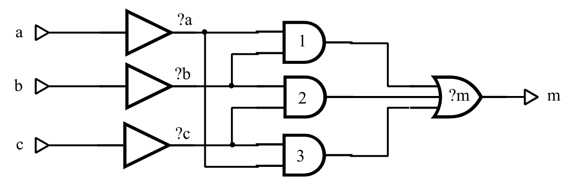
t=majority i=a,b,c o=m
  p=a t=and i=a
  p=b t=and i=b
  p=c t=and i=c
  p=1 t=and i=?a,?c
  p=2 t=and i=?a,?b
  p=3 t=and i=?b,?c
  p=?m t=or i=1,2,3
Figure 51 Majority Cell Illustrating Fault Filtering
A filter is set up with the NO prefix and the STRING (STRI) keyword option (the NO prefix specifies “do not include names of the specified type”). The following command directs SIMIC to utilize numeric filtering:
NO FAULT STRING=&NUMERICAny prefix of the word NUMERIC is valid (e.g., &N, &NU, etc.).
Caution: SIMIC will also accept NUMERIC, without the leading &. This would be another valid name-based filter whose effects are entirely different from &NUMERIC. See Filtering With Pattern Strings below.
Filtering will occur when subsequent faults are selected with the LIST, INPUT, OUTPUT, or LFILE keywords.
Note that the hierarchical part name of the instantiated majority cell need not be numeric; only the lowest component of the part name is relevant. For example, suppose that an instance of this cell is:
p=maj t=majority i=a,b,c o=mThe names of the internal 2-input AND gates will be maj.1, maj.2, and maj.3; the lowest components of these hierarchical names are all numeric. If the commands:
NO FAULT STRING=&NUMERIC
FAULT LIST:
are issued, then all faults except the input and output faults at these three parts will be selected.
Referring to Figure 51, there are other internal faults that have not been excluded by the numeric part name filter. These are faults at the three signals that drive the inputs of the 2-input AND gates and input faults at the OR gate. Since these signals and the OR gate have been assigned names that contain question marks, the default SIMIC string filter removes these faults as well. Therefore, no internal faults will be included in the simulation.
A filter can be removed (disabled) by re-specifying it without the NO prefix:
FAULT STRING=&NUMERICFilters can be introduced and removed as necessary. For example, the run command sequence:
FAULT STRING=&NUMERIC
FAULT LIST=a.();
FAULT STRING=&NUMERIC
FAULT LIST=b.();
selects input and output faults at all parts whose names begin with “a.” except those that have numeric components at the lowest hierarchical level. and input and output faults at all parts whose names begin with “b.” regardless of the lowest hierarchical components of their names.
In addition to numeric part name filtering, SIMIC also supports filtering of signals whose generating elements have alphanumeric (non-numeric) part names. This filter is introduced with the command:
NO FAULT STRING=&ALPHANUMERICAny prefix of the word ALPHANUMERIC is valid (e.g., &A, &AL, etc.).
This filter is removed with the command:
FAULT STRING=&ALPHANUMERICThe &NUMERIC and &ALPHANUMERIC filters are complementary; specifying both would filter all subsequently-specified faults. SIMIC issues a warning message if both filters are activated, and will perform the filtering.
Filtering With Pattern Strings
The second type of name-based filter operates as a template or pattern on part and signal names. Here, the complete hierarchical name is used, not just the last component. If a part name contains the pattern, all input faults are filtered. If a signal name contains this pattern, its associated faults are filtered.
Pattern-based filters are activated with the command: NO FAULT STRING=<template>
The simplest form of <template> is a character string, possibly quoted. For example, the command:
NO FAULT STRING=andwould filter all signals whose names contain the substring “and”. Thus, if a circuit contains two instances of the full-adder cell illustrated in Figure 39 (page 191):
p=a t=full-adder i=a1,b1,cin1 o=s1,cout1 p=b t=full-adder i=a2,b2,cin2 o=s2,cout2then the command:
FAULT LIST:will select all faults in both instances except the input faults of the 2-input AND gates named a.and1, a.and2, a.and3, b.and1, b.and2, and b.and3, and their output faults, since the output signals have the same names as the gates.
A filter pattern can be removed (disabled) by re-specifying it without the NO prefix:
FAULT STRING=<template>Filters can be introduced and removed as necessary. For example, in the two full-adder instances above, the run command sequence:
NO FAULT STRING=and
FAULT LIST=a.()
FAULT STRING=and
FAULT LIST=b.()
selects all signal faults in part a except those associated with the signals a.and1, a.and2, and a.and3, and selects all signal faults in part b.
SIMIC does not assign any significance to the filter pattern. For example, the command:
NO FAULT STRING=NUMERICwould cause all subsequently specified faults associated with signals and parts whose names contain the substring “NUMERIC” to be filtered from simulation.
Templates such as “and” are not good choices for filters, since this character sequence is likely to be used within names. For example, this template would cause the signal operand.sum to be filtered from simulation, since “and” is a substring of “operand”.
Note that the SIMIC default filter pattern is:
NO FAULT STRING=’?’The general form of <template> is: <repetition> * <character-string>
where <repetition> is an integer specifying the minimum number of repetitions of the character string <character-string>. Optional spaces may be placed before or after the delimiting asterisk. For example:
NO FAULT STRING=2*’?’would cause filtering of subsequently specified signals whose names contain two or more question marks, regardless of their distribution.
Note: SIMIC would not accept the above 2-question-mark filter pattern if the default pattern is still active, since the default pattern covers this pattern. That is, any character string containing two question marks also satisfies the match for the default pattern of a single question mark. To activate the pattern of two question marks, the default should be cancelled first:
FAULT STRING=’?’
NO FAULT STRING=2*’?’
As another example:
NO FAULT STRING=3*’.’would cause filtering of faults at hierarchical depths greater than 2.
SIMIC supports a maximum of five simultaneously-active filter patterns.
Switch-Level And Tristating Components
Most faults at the control (gate) inputs and the outputs of switch-level and tristating components (BTGs, BTGRs, TGATEs, TINVs, TPADs, and UTGRs) are either undetectable or only potentially-detectable. These faults typically cause signals to tristate when they are driven in the fault-free circuit, or introduce contention between pullup and pulldown transistors.
Including Switch-Level Faults
By default, SIMIC does not include faults at the control inputs of BTGs, BTGRs, TGATEs, TINVs, and UTGRs.
The INCLUDE (INC) keyword of the FAULT command specifies whether faults at switch-level and tristating components should be included in the simulation. The commands
FAULT INCLUDE=TRISTATE-ENABLESor
FAULT INCLUDE:direct SIMIC to include these faults.
The NO prefix can be used with either command form to restore the default SIMIC operation of excluding these faults.
The number of switch-level control faults excluded from simulation is reported in the terminal output as “Total Excluded Faults” under the category “At Enables”. For example, referring to Figure 52 (page 224), 1350 faults were excluded from consideration in the circuit being simulation because they were associated with control inputs of switch-level or tristating components.
Sensing Tristate Values At Primary Outputs And Busses
Most modern testers can test for undriven (floating) device outputs by measuring output impedance; these testers can therefore detect faults that cause outputs to be driven when they would be undriven in the fault-free circuit.
By default, SIMIC does not assume that the tester can measure output impedance. Thus, it does not compare the output of a faulty circuit with the fault-free output if the latter is undriven. SIMIC can be directed to make this comparison with the TRITEST (TR) keyword of the FAULT command:
FAULT TRITEST:In this test mode, when a fault-free output tristates, SIMIC will:
Mark a fault as potentially-detected if it is uncertain whether the cor-responding faulty output will tristate.
Mark a fault as detected if the corresponding faulty output will be driven (even if the driven value is unknown).
If the TRITEST test mode is specified, the default SIMIC operation of not testing tristating outputs can be restored with the NO prefix:
NO FAULT TRITEST:Statistical Fault Simulation
Since fault simulation can require a considerable amount of CPU time, it is often desirable to obtain a “quick” estimate of the fault coverage of a large set of test stimuli for a complex circuit. Statistical fault simulation, or selection of a random fault sample for simulation, offers this capability. The sample size should be large enough to provide good estimates of the fault coverage and the sections of the circuit that remain untested. In general, samples containing at least 1000 faults should confine the sampling error to 3%.
Selecting Fault Samples
The FAULT command’s SAMPLE (SA) keyword instructs SIMIC to generate a random sample of faults that were previously selected with the LIST, INPUT, OUTPUT, or LFILE keywords:
FAULT SAMPLE=<percent>%
where <percent> is an integer between 1 and 100 inclusive. The percent
sign (%) is optional.
By default, the sample is taken from the complete set of selected faults. SIMIC can be directed to generate the random sample from the collapsed set instead with the COLLAPSED keyword value:
FAULT SAMPLE=<percent>%,COLLAPSED
Any prefix of this word is valid. For example,
FAULT SAMPLE=20%,COdirects SIMIC to generate a 20% random sample from the collapsed set of faults.
The sample space specification is “sticky”; in order to return to the default sample space of all selected faults, use the command
FAULT SAMPLE=<percent>%,SELECTED
The random number generator that selects the sample uses a starting value, or seed, derived from the real-time clock. SIMIC always reports the seed in the terminal output. Sometimes, it is desirable to repeat a simulation exactly, for debugging purposes; to do so, the seed must to be set to the desired value (i.e., the seed of the run being replicated). This may be done by specifying the desired seed after either the sample percentage or the COLLAPSED or SELECTED options:
FAULT SAMPLE=<percent>%,<seed>
or
FAULT SAMPLE=<percent>%,COLLAPSED,<seed> where <seed> is the desired (integer) value of the seed.
For example, Figure 52 Figure 35 (page 224) illustrates the terminal output of a fault simulation run in which a 10% sample of all selected faults was requested, and the random number generator seed happened to be 540,957. Either of the commands
FAULT SAMPLE=10,540957or
FAULT SAMPLE=10,SELECTED,540957will replicate this run.
Note: the sample percentage, <percent>, must always be the first item specified for the SAMPLE keyword.
Selecting The Confidence Level
Whenever a fault sample is simulated (<percent> < 100), SIMIC estimates a confidence interval, or range of values, for the fault coverage over the entire sample space. By default, this interval, centered at the sample’s fault coverage (except near the 0% and 100% extremes), is at the 95% confidence level; that is, the probability is 0.95 that the actual fault coverage over the entire sample space lies within this interval.
SIMIC can be directed to estimate this interval at another confidence level with the CONFIDENCE (CONFI) keyword:
FAULT CONFIDENCE=<level>%
where <level> is an integer between 90 and 99 inclusive. The percent (%) sign is optional.
For example:
FAULT LIST: SAMPLE=20% CONFIDENCE=98%directs SIMIC to generate a 20% random sample of all faults in the circuit and estimate a possible range of values for the fault coverage with respect to the complete set of faults at the 98% confidence level. This interval would be wider than the corresponding interval at the 95% confidence level.
Note: The confidence interval will be inaccurate if very small samples are used (< 100 faults). Also, the confidence interval is calculated using a normal approximation to the actual (hypergeometric) sampling distribution. Thus, this interval will tend to be slightly pessimistic (too wide) for large samples (> 75%).
Example – Simulation Of A Random Fault Sample
Figure 52 (page 224) illustrates part of the terminal output of a simulation involving a random fault sample for a circuit. The fault sample was generated with the command:
FAULT LIST: SAMPLE=10%Referring to Figure 52:
- SIMIC reports the sample percentage, which faults were sampled
(selected vs. collapsed faults), and the random number generator seed:
Generating 10% Sample of Selected Faults Random Number Generator Seed is 540957
- After removing invisible faults and undetectable faults (including faults at enable inputs of tristating elements), the fault basis of this circuit is 21,720 faults (10,470 collapsed faults). SIMIC generates the
fault sample and reports its size:
10% Sample of Basis Faults = 2172 [ 1854 Collapsed]
Note: had the sample space been the collapsed set of faults, the sample would have contained 1,047 collapsed faults.
Referring to the box score:
- The fault selection and sample percentage are reiterated.
- The confidence level is reported (Confidence= 95%).
- Of the 2,172 faults, 1,154 were detected and 13 were potentially detected. In terms of the collapsed faults, 1,854 faults were simulated, of which 1006 were detected and 13 were potentially detected.
If potential detections are not counted in the fault coverage,
then the fault coverage for the selected sample is (1,154/2,172 =) 53.13%. The fault coverage with respect to all (21,720) selected faults is estimated to fall between 51.03% and 55.23% with a probability of 0.95.
Similarly, the fault coverage for the collapsed sample is (1,006/ 1,854 =) 54.26%. The fault coverage with respect to all (10,470) collapsed faults is estimated to fall between 51.99% and 56.53% with a probability of 0.95.
If potential detections are counted in the fault coverage, then (1154+13=) 1167 faults would be detected. The fault coverage for the selected sample is then (1,167/2,172 =) 53.73%. The fault coverage with respect to all (21,720) selected faults is estimated to fall between 51.63% and 55.83% with a probability of 0.95.
Similarly, (1006+13=) 1019 collapsed faults would be detected. The fault coverage for the collapsed sample is then (1,019/1,854 =) 54.96%. The fault coverage with respect to all (10,470) collapsed faults is estimated to fall between 52.70% and 57.23% with a probability of 0.95.
Incremental Test Generation With A Fault Sample
If the fault sample is “sufficiently” large, the sample faults that remain undetected or potentially-detected should indicate sections of the circuit that remain untested. Thus, one possible approach to incremental test generation that would reduce the amount of required CPU time is to use the untested sample faults to evaluate new test stimuli. This time, no sample would be generated; all untested faults of the previous iteration would be simulated. Thus, the LFILE keyword would be used to select the faults for each subsequent iteration:
FAULT LFILE=<file_name> or FAULT LFILE:
When an acceptable level of fault coverage is obtained in this manner, all faults would be simulated in the last phase of test generation.
Generating 10% Sample of Selected Faults Random Number Generator Seed is 540957
Generating 10% Sample of Selected Faults
Random Number Generator Seed is 110634

Fault Information for Circuit IPU
        Total Number of Faults =    23422 [   10537 Collapsed]
     Total Undetectable Faults
           Due To Invisibility =        4 [       1 Collapsed]
            Due To Power-Rails =      348 [       1 Collapsed]
         Total Excluded Faults
                    At Enables =     1350 [       1 Collapsed]

    Selected Fault Information =  Input+Output Faults

    Fault Basis For Simulation =    21720 [   10534 Collapsed]

10% Sample of Basis Faults  = 2172 [ 1868 Collapsed]

Fault simulation summary at end of Pass 1:
  Faults simulated this pass = 2172 [1868 collapsed]
  Faults detected this pass = 1163 [1002 collapsed]
  Faults potentially detected this pass = 11 [11 collapsed]
  Faults deferred this pass = 0 [0 collapsed]
**Cumulative faults simulated = 2172 [1868 collapsed]
**Cumulative faults detected = 1163 [1002 collapsed]
**Cumulative fault coverage = 53.55% [53.64% collapsed]

    ***********************************************************************
    ***********************************************************************
    **                                                                   **
    **                 Fault Analysis Report for Design:                 **
    **                                IPU                                **
    **                                                                   **
    ** Faults Simulated: Input + Output Faults; 10% Random Sample        **
    ** Options: Pdetect= Resolve, Keep Potentially Detected Faults       **
    **          Confidence= 95%                                          **
    **                                                                   **
    **                        |      SELECTED      |     COLLAPSED       **
    **                        |      --------      |     ---------       **
    **  Faults Simulated      |        2172        |        1868         **
    **  Actual Detects        |        1163        |        1002         **
    **  Potential Detects     |          11        |          11         **
    **  Fault Coverage        |   53.55% - 54.05%  |   53.64% - 54.23%   **
    **                                                                   **
    **                Fault Coverage Confidence Intervals                **
    **                                                                   **
    **  Detects               |   51.45% - 55.64%  |   51.38% - 55.90%   **
    **  Detects + Potentials  |   51.96% - 56.15%  |   51.97% - 56.49%   **
    **                                                                   **
    ***********************************************************************
    ***********************************************************************
Figure 52 Example – Terminal Output for a Random Fault Sample
Using Sensitization Information
Unsensitized faults are excluded, but they are not suppressed; they are included in the denominator of the Fault Grade.
Fault simulation time could be reduced if the results of sensitization analysis performed during good-logic simulation were available. This information eliminates the overhead of carrying the unsensitized faults during simulation, since they are known in advance to be undetected by the test stimuli.
Obviously, the sensitization analysis run and the fault simulation run must be consistent; both simulations must use the same test stimuli.
By default, SIMIC does not utilize the results of sensitization analysis to remove faults from simulation. The FAULT command’s UFILE (UF) keyword directs SIMIC to do so. The command:
FAULT UFILE=<file_name>
informs SIMIC that the specified file contains the names of unsensitized faults. If no file extension is specified, the default extension of this file is .uns. Similarly, the command:
FAULT UFILE:directs SIMIC to read the file with default file name and extension .uns for the names of the unsensitized faults.
The simulation results will be the same regardless of whether unsensitized faults are included in, or excluded from, simulation. However, two reports will differ:
The box score will contain the number of unsensitized faults excluded from simulation.
The “Undetected And Potentially Detected Faults” report will contain two categories:
- “Sensitized Faults” – faults that were sensitized, but were either undetected or potentially-detected during simulation.
- “Unsensitized Faults” – faults that were unsensitized and undetected.
As an example, the following run commands are identical to those in the example above, except another FAULT command has been added to exclude unsensitized faults and to report undetected faults:
define file=fadder
get type=full-adder
define padder.3 = 000 110 011 111 1X1 apply patterns=padder fault list:
nofault list=xor;i1,xor;i2,xor;i3
fault ufile: report=undetected
simulate
quitFigure 53 illustrates the resulting report file. Note that the box score contains an additional entry, “Unsensitized Faults”, indicating that two unsensitized faults were excluded from simulation (see the corresponding report in Figure 53, page 35, for comparison). Also, these faults, AND2;I1-@-1 and AND3;I2-@-1, are reported separately in the “Undetected And Potentially Detected Faults” category.
Since sensitization analysis could be used in incremental test generation, an alternative search path exists for the UFILE keyword if the UFILE specification (<file_name>) does not contain a path name, and if auto-numbered directories are being used (see Incremental Test Generation). In this case, SIMIC searches the output fault directory for the unsensitized faults file. If this file is not found, the current directory is then searched.
Note: the output fault directory is used, rather than the previous fault directory (which is searched for the file specified by the LFILE keyword), since the sensitization analysis is associated with the current test stimuli, rather than the previous test stimuli (as is the incremental test generation file specified by the LFILE keyword).
From a procedural standpoint, the most convenient method of including sensitization analysis in incremental test generation is to utilize auto-numbering in both the fault-free simulation session that performs the sensitization analysis and the fault simulation session that reads this information.
For example, suppose that the directory fadder.f00 exists, and sensitization analysis will be performed for the next incremental test stimulus set. Either of the commands:
sensitize directory: list: ufile:or
sensitize directory=fadder.f__ list: ufile:would cause the directory fadder.f01 to be created by this session and the .uns file to be placed in this directory (see Sensitization Analysis for a description of the SENSITIZE command). For the subsequent fault simulation session, the commands to read the incremental test generation file from subdirectory fadder.f00 and the sensitization analysis from subdirectory fadder.f01, and to write the simulation results to subdirectory fadder.f01 would be:
fault directory=fadder.f_
fault lfile: ufile: report=undetected
Remark= ‘Fault’ Created by SIMIC Version 1.01.00 on Tue Aug 31 11:45:26 1993
***********************************************************************
***********************************************************************
** **
** Fault Analysis Report for Design: **
** FULL-ADDER **
** **
** Faults Simulated: Selected Faults **
** Options: Pdetect= Resolve, Keep Potentially Detected Faults **
** Confidence= 95% **
** **
** | SELECTED | COLLAPSED **
** Faults Simulated | 32 | 17 **
** Unsensitized Faults | 2 | 2 **
** Actual Defects | 24 | 12 **
** Potential Detects | 4 | 1 **
** Fault Coverage | 70.59& - 82.35% | 63.16% - 68.42% **
** **
***********************************************************************
***********************************************************************
Sensitized Faults:
*(AND1-@-0 [1]) (AND;I1-@-0 [1]) *AND1;I1-@-1 (AND1;I2-@-0 [1])
*AND1;I2-@-1 *AND2;I2-@-1 *AND2;I1-@-1 (OR1;I1-@-0 [1])
Unsensitized Faults:
*AND2;I1-@-1 *AND3;I2-@-1Figure 53 Report File for the Full Adder with Unsensitized Faults
Storage Management
If the amount of fault storage is insufficient to simulate all faults, SIMIC partitions the faults and executes multiple passes to complete the simulation.
Since the amount of storage required to simulate each fault is unpredictable, SIMIC might sometimes overestimate the number of faults that can be simulated with the given amount of storage; in this case, faults will be dropped from the current pass and re-simulated in a subsequent pass. These faults are called deferred faults. Alternatively, SIMIC might sometimes underestimate the number of faults that can be simulated with the given amount of storage. For both situations, SIMIC will modify its estimate of the number of faults it can simulate in subsequent passes.
At the end of each pass, SIMIC reports summary statistics at the terminal. These summaries contain complete and collapsed counts of the number of faults simulated, detected, potentially-detected, and deferred in the pass, as well as cumulative counts of the number of faults simulated, the number of faults detected, and the fault coverage. For example:
Fault simulation summary at end of Pass 2:
  Faults simulated this pass = 124 [111 collapsed]
  Faults detected this pass = 64 [59 collapsed]
  Faults potentially detected this pass = 1 [1 collapsed]
  Faults deferred this pass = 0 [0 collapsed]
**Cumulative faults simulated = 2172 [1891 collapsed]
**Cumulative faults detected = 1181 [1029 collapsed]
**Cumulative fault coverage = 54.37% [54.42% collapsed]
Note: the fault coverage in each pass will usually be close to the final fault coverage at the end of the run, and the cumulative fault coverage at the end of each pass should “home in” on this value. Thus, the fault coverage summaries at the end of each pass are fair estimators of the final fault coverage.
Specifying Fault Simulation Storage
The default fault simulation storage of 300,000 words should be sufficient for small circuits (< 1,000 primitive parts). When this storage is inadequate, SIMIC will issue a message that the amount of storage is insufficient for generating the faults or for simulating them, and abort fault simulation. When this occurs, the fault storage must be increased.
The STORAGE (STOR) keyword of the FAULT command specifies the amount of memory, in four-byte words, that should be used for fault simulation.
FAULT STORAGE=<storage>
where <storage> is an integer. The default is equivalent to FAULT STORAGE=300000
While there is some overhead in executing multiple passes, this overhead is not significant; if a given amount of storage allows simulation to be completed in, say, 20 passes, the amount of CPU time saved by using 20 times this storage to complete simulation in one pass will be a small fraction of the total CPU time. The determining factor that affects CPU time is the total number of faults being simulated; for a given set of test stimuli, the two are (essentially) linearly related.
Note: it is possible to specify too much storage; if the specified value exceeds the amount of real storage that is available for the run, and if there are enough faults to fill this storage, considerable page faulting could result. This would drastically increase execution time. On UNIX and VMS, and other systems that support aquiring resource informations, SIMIC reports the system CPU time and the number of page faults at the end of each run, making it easy to determine whether this situation has occurred.
Specifying The Number Of Faults To Be Simulated Concurrently
The CONCURRENT keyword (CONC) of the FAULT command specifies the number of faults SIMIC should simulate concurrently in the first pass:
FAULT CONCURRENT=<n>
where <n> is an integer.
If this number is not specified, SIMIC estimates it from the amount of fault storage available. Regardless of whether the number of faults simulated in the first pass is user-specified, as above, or is internally estimated, SIMIC will dynamically adjust the number of faults to be simulated in subsequent passes, as described above.
If, however, an exclamation mark (!) immediately follows the concurrent specification:
CONCURRENT=<n>!
then the number of fault simulated in all passes will be limited to this specification, even if SIMIC estimates that more faults could be simulated per pass. If the specified concurrency causes faults to be deferred, SIMIC will reduce the number of faults per pass below this level.
Progress Reports
Fault simulation is CPU-intensive, and a large amount of time may be required to simulate all faults in a complex circuit. While SIMIC issues a summary report at the end of each pass, even these reports could be spaced over long time intervals. Thus, it might be reassuring if messages were issued more frequently indicating that faults are being detected.
The REPORT keyword can be used to direct SIMIC to issue progress messages within each pass whenever a fault is detected or potentially-detected:
FAULT REPORT=PROGRESSAny prefix of the word “PROGRESS” can be used. Unlike all other output generated by the REPORT keyword, progress reports are directed to the terminal.
The following illustrates progress reports for the modified Johnson counter simulation with then RESOLVE option (see Figure 50, page 214):
Note: progress report items in square brackets represent distinguishable (collapsed) counts:
At start of Pass 1, simulating 36 [26] faults:
At Test 2/Pass 1..........   Det=6[3]         Pot=6[5]                     Cum=6/36(=16.67%) [3/26(=11.54%)]
At Test 4/Pass 1..........   Det=3[2]         Pot=2[2]                     Cum=9/36(=25.00%) [5/26(=19.24%)]
At Test 6/Pass 1..........   Det=3[2]         Pot=2[2]                     Cum=12/36(=33.34%) [7/26(=26.93%)]
At Test 8/Pass 1..........   Det=11[7]        Pot=-4[-4]                   Cum=23/36(=63.89%) [14/26(=53.85%)]
At Test 10/Pass 1.........   Det=5[5]         Pot=-2[-2]                   Cum=28/36(=77.78%) [19/26(=73.08%)]
At Test 12/Pass 1.........   Det=5[5]         Pot=-2[-2]                   Cum=33/36(=91.67%) [24/26(=92.31%)]
At Test 14/Pass 1.........   Det=1[1]         Pot=0                        Cum=34/36(=94.45%) [25/26(=96.16%)]
At Test 20/Pass 1.........   Det=2[1]         Pot=-2[-1]                   Cum=36/36(=100.00%) [26/26(=100.00%)]
Each progress message contains the test number, the pass number, the number of faults detected and potentially-detected that test, and cumulative fault coverage. Numbers in square brackets describe collapsed faults. For example, in Test #4, three faults (two collapsed faults) were detected and two faults were potentially-detected. Note that in some messages, the reported number of potential detections is negative; these entries correspond to faults that were potentially-detected in previous tests and have become detected in the current test. For example, five faults were detected in Test #10, two of which were potentially-detected in previous tests.
Sometimes, long test sequences are required to detect a single fault, so it is possible that the time interval between progress messages could be long. Suffixing the PROGRESS option with an integer directs SIMIC to output progress messages over the specified test interval even if no faults have been detected or potentially-detected. For example
FAULT REPORT=PROG50causes SIMIC to issued progress messages whenever faults are detected or potentially-detected, or whenever 50 tests have elapsed since the last progress message. In progress messages of the latter type, the “Det=” and “Pot=” fields are blank.