Sensitization Analysis
Fast pre-pass analysis to determine which faults can potentially be detected.
Overview
Fault Sensitization Analysis is invoked with the SENSITIZE (SEN) command. This analysis is performed during fault-free simulation, which is initiated by a subsequent SIMULATE command. Sensitization analysis provides a quick methodology for estimating how thoroughly the test stimuli "exercise" the circuit. Fault simulation would be performed only after the test stimuli have been enhanced to achieve an acceptable level of fault sensitization.
In addition to specifying that fault sensitization analysis be performed, the SENSITIZE command can also direct SIMIC to selectively generate:
- Reports that list all sensitized faults, all unsensitized faults, all faults that are topologically invisible or are masked by power-rail connections, and the fault equivalence (collapsed) groups.
- A file containing all unsensitized faults that can be read in a subsequent fault simulation session. This information helps reduce fault simulation time, since the overhead of carrying the unsensitized (and therefore undetected) faults is eliminated.
Since the test stimuli are being verified rather than the design, the fault-free simulator does not support all of its design verification capabilities when sensitization analysis is being performed. In particular, the XPROPAGATE command options are not supported and timing checks are not performed for functional elements.
Description Of Sensitization Analysis
SIMIC performs local sensitization analysis, at the element level. A fault is locally sensitized if:
- the fault causes an element output to differ from its fault-free value, and,
- the fault-free value of the output signal is known.
Sensitization analysis is performed for both input and output faults. For example, consider the 2-input AND gate, G1, shown in Figure 33. If this gate's input state is:
-
a=1, b=1, then d=1 and e=1.
The faults G1;I1-@-0 (the first input of G1 stuck-at-0), G1;I2-@-0, and d-@-0 are locally sensitized at part G1, since any of these faults would cause signal d to differ from its known fault-free value of 1. At part G2, the output fault e-@-0 is sensitized; also, if c=0, then the fault G2;I2-@-0 is sensitized.
-
a=0, b=1, then d=0 and e=c.
The faults G1;I1-@-1 and d-@-1 are locally sensitized at part G1, since any of these faults would cause signal d to differ from its known fault-free value of 0. If c=0, the faults G2;I1-@-1, G2;I2-@-1, and G2-@-1 are locally sensitized at part G2, and if c=1, the faults G2;I1-@-0 and G2-@-0 are locally sensitized.
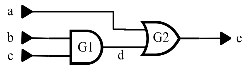
Figure 33: Two-Input And Gate Sensitization Example
A fault must be locally sensitized in order to be detected. For example, the fault d-@-0 is locally sensitized when signal d is logical 1. This fault could never be detected if signal d always remained logical 0 (or X), that is, if it were never sensitized.
Although local sensitization is necessary for detection, it is not sufficient. For example, even if signal d becomes logical 1, the fault d-@-0 may never propagate to a visible output (to be detected) if signal c is also logical 1 at the time; the effect of the fault would be blocked at OR gate G2.
Even though local sensitization is restricted to the fault site, SIMIC can sometimes “look ahead” and determine whether a locally sensitized fault is blocked from further propagation. It can do so when the element output at the fault site drives only a single load. If the fault is blocked at this load, SIMIC will not mark the fault as sensitized. For example, if signal c is logical 1 when signals a and b are logical 1, the faults G1;I1-@-0, G1;I2-@-0, and d-@-0 will not be marked as sensitized.
Sensitization vs. Detection
As described above, a fault must be locally sensitized in order to be detected. The difference between sensitization and detection can be summarized as follows1:
- Sensitization is necessary for detection, but not sufficient. The faulty element output value must still be propagated to a primary output.
- Sensitization analysis verifies local sensitization.
- Fault simulation verifies detection.
- For combinational circuits, it is possible to extend sensitization analysis to follow propagation of faults to primary outputs. For this case, the sensitization analysis would indeed be equivalent to fault simulation.
Analyzed Element Faults
SIMIC performs sensitization analysis for all net (signal) faults; this is commonly known as a toggle test. It also performs sensitization analysis for the input faults of all built-in primitives except the switch-level elements (BTGP, BTGN, BTGRP, BTGRP, TGATE), Booleans, and functional blocks (ROM, RAM, PLA).
Performing Sensitization Analysis
The LIST keyword of the SENSITIZE command directs SIMIC to perform sensitization analysis for all faults in the circuit:
SENSITIZE LIST:By default, the fault-free simulator does not perform sensitization analysis. Having issued the above command, sensitization analysis can be disabled with the NO prefix:
NO SENSITIZE LIST:After performing sensitization analysis for the test stimuli, SIMIC writes a box score to the terminal summarizing the results of the run.
By default, SIMIC also creates a file containing the names of all unsensitized faults; this file can subsequently be read during fault simulation. The unsensitized faults file has the default file name and the default extension of
.uns. The UFILE (UF) keyword can be used to explicitly specify the file’s name:
SENSITIZE UFILE=<file_name>
Note that <file_name> can specify a path name as well as a file extension when the file name is enclosed in quotes. The command form:
SENSITIZE UFILE:is equivalent to specifying the file’s default name. The NO prefix inhibits creation of this file:
NO SENSITIZE UFILE:Report Options describes the report options supported by SIMIC.
By default, the unsensitized faults file is written to the current directory. Alternatively, this file can be written to a user-specified directory; this is especially useful for incremental test generation (see Using Sensitization Analysis In Incremental Test Generation Using Sensitization Analysis In Incremental Test Generation).
Example – Sensitization Analysis For A Small Combinational Circuit
This section illustrates sensitization analysis for a simple combinational circuit, and describes the resulting SIMIC terminal output and unsensitized faults file.
The example uses the full-adder circuit of Figure 34 and the following run commands:
define file=fadder
get type=full-adder
define padder.3 = 000 110 011 111 1x1
apply patterns=padder
print list=a,b,c-in*c-out,sum
sensitize list: ufile=myfile
simulate
quit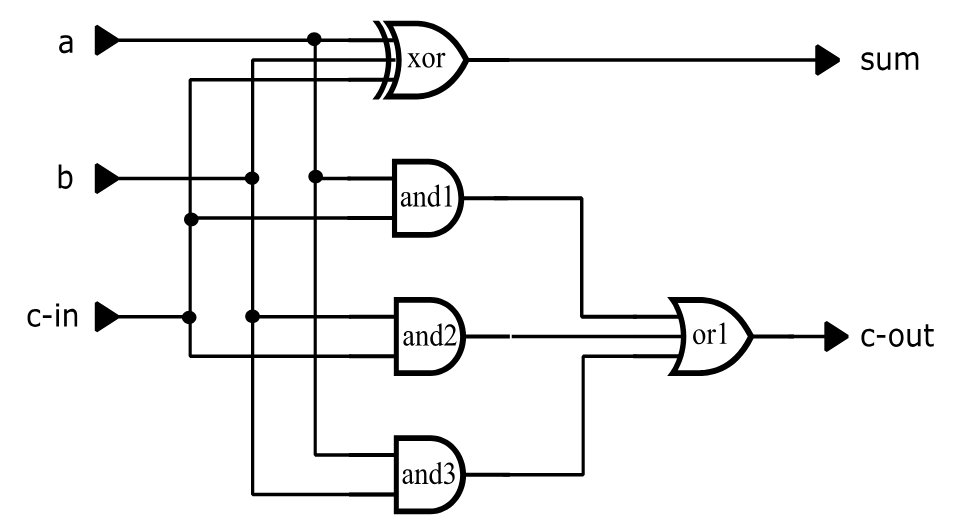
type = full-adder i=a,b,c-in o=sum, c-out
p=xor t=exor i=a,b,c-in o=sum
p=and1 t=and i=a,c-in
p=and2 t=and i=b,c-in
p=and3 t=and i=a,b
p=or1 t=or i=and1,and2,and3 o=c-out
Figure 34: Full-Adder Circuit (fadder.net)
The terminal output for this run is shown in Figure 35.
Main Get Network : FULL-ADDER
Using file: "fadder.net"
GET completed, Circuit totals:  Parts = 5; Signals = 10
   Inputs = 3; Busses = 0; Outputs = 2
Main Get Timing : TYPICAL Circuit Delays

Fault Information for Circuit FULL-ADDER
        Total Number of Faults =       40 [      25 Collapsed]
     Total Undetectable Faults
           Due To Invisibility =        0
            Due To Power-Rails =        0

    Selected Fault Information = All Input+Output Faults

    Fault Basis For Simulation =       40 [      25 Collapsed]

Remark= Options: (Fault Sensitize Simulation)
Remark=   Pattern Stimuli, Near Filter, Spike Filter
Remark=   Stable After Decay, Dynamic Delay, No Charge Sharing

C=                 ABC CS
C=                   - -U
C=                   I OM
C=                   N U
C=                     T

        0 T     1: 000 00
        0 T     2: 110 10
        0 T     3: 011 10
        0 T     4: 111 11
        0 T     5: 1X1 1X

    ***********************************************************************
    ***********************************************************************
    **                                                                   **
    **             Sensitization Analysis Report for Design:             **
    **                             FULL-ADDER                            **
    **                                                                   **
    **                        |      SELECTED      |     COLLAPSED       **
    **                        |      --------      |     ---------       **
    **  Faults in Circuit     |         40         |         25          **
    **  Faults Analyzed       |         40         |         25          **
    **  Faults Unsensitized   |          2         |          2          **
    **  Maximum Fault Coverage|         95%        |         92%         **
    **                                                                   **
    ***********************************************************************
    ***********************************************************************
Figure 35: Terminal Output For Full-Adder Sensitization Analysis.
Referring to the terminal output shown in Figure 35:
-
SIMIC provides a summary report on all the faults in the circuit:
Fault Information for Circuit FULL-ADDER
In this example, there are 40 single-stuck faults, and they fall into 25 collapsed groups (numbers in square brackets always refer to the collapsed fault set). There are no invisible faults and no faults that are undetectable because of power-rail connections.
-
All faults are selected for sensitization analysis. SIMIC reports the selection and the number of faults that remain after all undetectable faults have been removed from consideration:
Selected Fault Information = All Input+Output Faults
Fault Basis For Simulation = 40 [ 25 Collapsed]
-
After sensitization analysis has been completed, SIMIC outputs the box score summarizing the run. Results are given for both the complete set and the collapsed set of faults:
Faults in Circuit – this is the fault basis, i.e., the number of faults remaining after all undetectable faults have been removed. In this example none were removed; there are 40 faults in the complete set and 25 in the collapsed set.
Faults Analyzed – this is the number of analyzed faults. SIMIC only performs sensitization analysis for faults at supported primitive elements (those listed in Section 3.1.1.2 Analyzed Element Faults), Since, in this example, all elements are supported, all faults in the fault basis were analyzed.
Faults Unsensitized – this is the number of analyzed faults that were found to be unsensitized. In this example two faults were unsensitized (in both the complete and collapsed sets). These faults are written to the unsensitized faults file, which is myfile.uns in this example (since UFILE=MYFILE was specified in the SENSITIZE command).
Maximum Fault Coverage – this is an upper bound on the fault coverage; this coverage would be realized if all sensitized and all unanalyzed faults in the fault basis are detected:

For the complete set of faults, this is (40–2)/40 = 95%, and for the collapsed set of faults, it is (25–2)/25 = 92%.
The two unsensitized faults in the file myfile.uns are:
AND2;I1-@-1
AND3;I2-@-1
Report Options
The REPORT (REP) keyword of the SENSITIZE directs SIMIC to generate reports pertaining to the circuit's faults. The RFILE ( RF) keyword specifies the file to which the reports should be written. By default, the report file is written to the current directory. Alternatively, this file can be written to a user-specified directory; this is especially useful for incremental test generation (see Using Sensitization Analysis In Incremental Test Generation Using Sensitization Analysis In Incremental Test Generation).
Specifying The Report File
By default, SIMIC writes the sensitization analysis reports to a file whose name is the default file name and whose extension is .rps. This file can be explicitly specified with the RFILE (RF) command:
SENSITIZE RFILE=<file_name>
The command form:
SENSITIZE RFILE:specifies that the reports should be written to the file with the default name.
The NO prefix inhibits creation of the report file:
NO SENSITIZE RFILE:Once inhibited, either of the above two command forms (without the NO prefix) re-enables report file creation.
Specifying The Reports To Be Generated
The REPORT keyword supports options to selectively write any of five reports to the report file:
- The box score – selected with the SCORE option.
- The fault equivalence classes (fault collapsing) – selected with the EQUIVALENCES option.
- The suppressed faults – selected with the SUPPRESSED option.
- All analyzed faults that were unsensitized – selected with the UNSENSITIZED option.
- All analyzed faults that were sensitized – selected with the SENSITIZED option.
By default, only the box score is written to the report file. All other reports must be explicitly specified.
Different options can be combined in the same command. For example,
SENSITIZE REPORT=EQUIVALENCES,UNSENSITIZED specifies that the fault equivalences and the unsensitized faults be written to the report file.
Each of the options can be abbreviated to a prefix containing three or more characters. Thus, the above command could have been specified as:
SENSITIZE REPORT=EQU,UNSEThe colon form of the REPORT keyword is a shorthand way to specify all the reports:
SENSITIZE REPORT:The NO prefix can be used to selectively disable reports when the list form of the REPORT keyword is used. For example, the command sequence:
SENSITIZE REPORT:
NO SENSITIZE REPORT=EQUIV,SCO
specifies that all reports be generated except the fault collapsing report and the box score.
The NO prefix disables all reports when the colon form of the REPORT key-word is used:
NO SENSITIZE REPORT:Description Of The Reports
The Box Score
The box score written to the report file is identical to that written to the terminal.
The Fault Equivalence Report
The fault equivalence report presents the fault collapsing information in two ways:
- arranged by equivalence class – each equivalence class is assigned a numerical index, and all faults in the group are listed alphabetically.
- arranged by fault name – the faults are listed alphabetically, along with the numerical indexes of their equivalence classes, enclosed within curly braces.
Figure 36 illustrates the fault equivalence report for the full-adder circuit. The first part of the report organizes this information by equivalence class (their ordering is arbitrary). The 40 faults were collapsed into 25 classes; most classes contain only a single fault, but some (Group #12 through Group #15) contain multiple faults. The second part of the fault organizes this information by fault name. Alongside each fault name is the numerical index of the equivalence group containing that fault. For example, the entry A-@-0{1} indicates that the fault A-@-0 belongs to equivalence class #1.
**** List of Equivalent Faults by Group ****

Equivalence Group 1:
A-@-0

Equivalence Group 2:
A-@-1

Equivalence Group 3:
B-@-0

Equivalence Group 4:
B-@-1

Equivalence Group 5:
C-IN-@-0

Equivalence Group 6:
C-IN-@-1

Equivalence Group 7:
XOR;I3-@-1

Equivalence Group 8:
XOR;I3-@-0

Equivalence Group 9:
AND1;I1-@-1

Equivalence Group 10:
AND1;I2-@-1

Equivalence Group 11:
C-OUT-@-0

Equivalence Group 12:
AND3-@-1     C-OUT-@-1     AND1-@-1     AND2-@-1
OR1;I1-@-1   OR1;I2-@-1    OR1;I3-@-1

Equivalence Group 13:
AND1;I2-@-0  OR1;I1-@-0    AND1-@-0     AND1;I1-@-0

Equivalence Group 14:
AND2;I2-@-0  OR1;I2-@-0    AND2-@-0     AND2;I1-@-0

Equivalence Group 15:
AND3;I2-@-0  OR1;I3-@-0    AND3-@-0     AND3;I1-@-0

Equivalence Group 16:
XOR;I2-@-1

Equivalence Group 17:
XOR;I2-@-0

Equivalence Group 18:
AND2;I1-@-1

Equivalence Group 19:
AND2;I2-@-1

Equivalence Group 20:
XOR;I1-@-1

Equivalence Group 21:
XOR;I1-@-0

Equivalence Group 22:
AND3;I1-@-1

Equivalence Group 23:
AND3;I2-@-1

Equivalence Group 24:
SUM-@-0

Equivalence Group 25:
SUM-@-1

         **** List of Equivalence Group Membership by Fault ****

A-@-0{1}          AND1;I1-@-0{13}        AND2-@-0{14}        AND2;I2-@-0{14}
AND3;I1-@-0{15}   B-@-0{3}               C-OUT-@-0{11}       OR1;I2-@-0{14}
SUM-@-0{24}       XOR;I2-@-0{17}         A-@-1{2}            AND1;I1-@-1{9}
AND2-@-1{12}      AND2;I2-@-1{19}        AND3;I1-@-1{22}     B-@-1{4}
C-OUT-@-1{12}     OR1;I2-@-1{12}         SUM-@-1{25}         XOR;I2-@-1{16}
AND1-@-0{13}      AND1;I2-@-0{13}        AND2;I1-@-0{14}     AND3-@-0{15}
AND3;I2-@-0{15}   C-IN-@-0{5}            OR1;I1-@-0{13}      OR1;I3-@-0{15}
XOR;I1-@-0{21}    XOR;I3-@-0{8}          AND1-@-1{12}        AND1;I2-@-1{10}
AND2;I1-@-1{18}   AND3-@-1{12}           AND3;I2-@-1{23}     C-IN-@-1{6}
OR1;I1-@-1{12}    OR1;I3-@-1{12}         XOR;I1-@-1{20}      XOR;I3-@-1{7}
Figure 36 (continued) Fault Equivalence Report For Full-Adder Circuit
The Suppressed Faults Report
The suppressed faults report contains:
- All faults that are inherently undetectable because they are topologically invisible.
- All faults that are inherently undetectable because of power-rail connections.
- All switch-level faults that are, by default, suppressed from fault simulation (see Section 3.2.10 Switch-Level And Tristating Components).
No faults are suppressed in the full-adder circuit. See Figure 3.2-6 (page 3.2-19) for an example of this report.
The Unsensitized Faults Report
This report lists all analyzed faults that were found to be unsensitized. In order to also represent this information in terms of the collapsed set of faults, one fault from each equivalence class is selected as the class’ representative fault, and is listed with a leading asterisk (*). All other faults in the equivalence classes are listed without the asterisk.
Figure 37 illustrates this report for the full-adder circuit. Two faults were found to be unsensitized, both were representative (and only) faults in their equivalence classes.
The Sensitized Faults Report
This report lists all analyzed faults that were found to be sensitized. As with the unsensitized faults report, in order to indicate the sensitized faults in terms of the collapsed set of faults, one fault from each equivalence class is selected as the class’ representative fault, and listed with a leading asterisk (*). All other faults in the equivalence classes are listed without an asterisk.
Figure 38 illustrates this report for the full-adder circuit. Thirty eight faults were found to be sensitized. In terms of the collapsed set, twenty three faults were sensitized (those with leading asterisks). For example, the four faults in Equivalence Group #15, AND3-@-0, AND3;I1-@-0, AND3;I2-@-0, and OR1;I3-@-0 were sensitized. The representative fault, AND3-@-0, is preceded with an asterisk while the other three faults are not.
Changing The Width Of The Report Files
By default, the maximum line width of the .rps file is 80 characters. This can be changed with the EXPAND (EX) keyword. The command
SENSITIZE EXPAND:expands the maximum line width of these files to 132 characters.
The NO prefix can be used to restore the default line width:
NO SENSITIZE EXPAND: **** List of Unsensitized Faults ****
*AND2;I1-@-1 *AND3;I2-@-1Figure 37: Unsensitized Faults Report For Full-Adder Circuit
                       **** List of Sensitized Faults ****
*A-@-0          *A-@-1         *AND1-@-0          AND1-@-1
AND1;I1-@-0     *AND1;I1-@-1   AND1;I2-@-0        *AND1;I2-@-1
*AND2-@-0       AND2-@-1       AND2;I1-@-0        AND2;I2-@-0
*AND2;I2-@-1    *AND3-@-0      AND3-@-1           AND3;I1-@-0
*AND3;I1-@-1    AND3;I2-@-0    *B-@-0             *B-@-1
*C-IN-@-0       *C-IN-@-1      *C-OUT-@-0         *C-OUT-@-1
OR1;I1-@-0      OR1;I1-@-1     OR1;I2-@-0         OR1;I2-@-1
OR1;I3-@-0      OR1;I3-@-1     *SUM-@-0           *SUM-@-1
*XOR;I1-@-0     *XOR;I1-@-1    *XOR;I2-@-0        *XOR;I2-@-1
*XOR;I3-@-0     *XOR;I3-@-1
Figure 38: Sensitized Faults Report For Full-Adder Circuit
Using Sensitization Analysis In Incremental Test Generation
Incremental test generation is the process of iteratively generating test stimulus sets to detect faults that eluded all previously-generated test sets. At the end of this process, the individual test stimulus sets are concatenated to form the complete test set.
Thus, incremental test generation requires multiple fault simulation sessions. If the results of each session were written to the current directory, previous results would be overwritten unless some renaming convention is followed. To avoid this possibility, the FAULT command supports a methodology for creating sequentially-numbered subdirectories so that the results of each session can be written to a unique directory.
Since sensitization analysis might be performed for each test set prior to fault simulation, this same methodology is supported for the SENSITIZE command. The DIRECTORY (DIR) keyword can be used to specify a directory to which the unsensitized faults file and the sensitization report file should be written. If this keyword is not specified, the files are written to the current directory.
See Section 3.2.6 Incremental Test Generation for a detailed description of the fault simulation directory options associated with incremental test generation, and for an example of inclusion of sensitization analysis results into this process.
Default Subdirectory Operation
With the default form of the DIRECTORY keyword, SIMIC always creates the output fault directory.
If the default form of the DIRECTORY keyword is specified:
SENSITIZE DIRECTORY:then SIMIC will always create a new, specially-named output fault directory, which will be a subdirectory of the current directory. The subdirectory name has the form:
<default_file>.fnn
where nn is a 2-digit decimal index from 00 to 99. If no subdirectory with this type of name exists, as would be the case the first time sensitization analysis is performed for a circuit, SIMIC writes the sensitization analysis output files to the subdirectory <default_file>.f00. If subdirectories with this type of name already exist, SIMIC will create a new subdirectory whose 2-digit index is 1 greater than that of the highest previously-existing directory.
For example, the sequence of subdirectories:
fadder.f00, fadder.f01, …
would be created for the full-adder circuit. Suppose that the subdirectory with the highest 2-digit index is fadder.f04. On the next iteration, SIMIC would create subdirectory fadder.f05 and write the sensitization analysis output files to this subdirectory.
Note: if more than 100 iterations are required to generate test stimuli, alter-native naming will be required; if <default_file>.99 exists, SIMIC will write the sensitization analysis output files to the current directory.
Default Operation With User-Defined Directory Names
If the DIRECTORY name ends with two underscores, SIMIC always creates the output fault directory.
If the path name specified with the DIRECTORY keyword ends with “__” (two underscore characters), SIMIC will also utilize the default subdirectory conventions, except with the user-defined prefix. For example, the command
SENSITIZE DIRECTORY=mydir__would cause the sequence of subdirectories mydir00, mydir01, … to be created. Note that the default subdirectory naming convention is equivalent to:
SENSITIZE DIRECTORY=<default_file>.f__
Since the DIRECTORY keyword accepts quoted strings, the specified directory path need not be a subdirectory of the current directory.
Using The Last Directory As The Output Fault Directory
If the DIRECTORY name ends with a single underscore, SIMIC does not create the output fault directory.
If the path name specified with the DIRECTORY keyword ends with a single underscore, SIMIC will not create a new subdirectory; the previously-existing subdirectory with the highest 2-digit index will be used as the output directory.
For example, if the command:
SENSITIZE DIRECTORY=mydir_is specified, and if the only existing subdirectories are mydir00, mydir01, and mydir02, then the sensitization analysis output files will be written to subdirectory mydir02.
Operation For Other User-Specified Directory Names
If the DIRECTORY name does not end with an underscore, SIMIC creates the output fault directory if it doesn't already exist.
If the path name specified with the DIRECTORY keyword does not end with an underscore (single or double), SIMIC will write the sensitization analysis output files to this directory. If the directory does not exist, SIMIC will create it.
For example, the command:
SENSITIZE DIR=mydir07specifies the sensitization analysis output directory as mydir07. If this subdirectory does not exist, SIMIC will create it.