Circuit Troubleshooting
Interactive debugging techniques and tools for isolating design errors and timing hazards.
Introduction
SIMIC offers a wide selection of commands to facilitate circuit debugging. Each command performs a unique function that, when combined with other SIMIC options, creates a powerful debugging environment that can be customized to the problem at hand.
Debugging Capabilities
- Detect specified conditions. This feature allows detection of a variety of events, such as signal change, presence of hazard conditions, reaching a specified test, and other situations. Upon the occurrence of the user-specified conditions, SIMIC can be instructed to issue a warning (using the
WARNcommand), and/or stop simulation (using theBREAKcommand). - Interrogate the state of the network. This feature allows values (with the
LOOKcommand) or parameters, such as delay (with the?command), to be requested for any signal, and forward (LOOK OUTPUT) or backward (LOOK INPUT) traversal through the circuit's topology. - Trace signal activity. Using the
TRACEcommand, activity at selected signals can be monitored. Causality information (why a signal changed) can be requested (with theTRACE EXPANDcommand). - Enable/Disable hazard and/or timing checks on a per node basis.
- Modify simulation parameters at run-time. This includes changing delay, decay, and node states (using the
CLAMPand/orSETcommands). - Simulate fragment. After a problem is localized, SIMIC allows restriction of actions to a small portion of the total simulation (with the
PRANGEoption) to prevent voluminous extraneous information. SIMIC also supports repetitive resimulation from a saved stable-state (RESTORE TNUMcommand), providing immediate feedback on modifications.
Examples
The following case study demonstrates practical application of SIMIC's debugging capabilities:
Divide-by-7 Counter Debugging
A complete debugging session demonstrating spike hazard detection and X-pulse propagation in a counter circuit.
SIMIC Terminology and Definitions
Combinational Timing Hazards
SIMIC performs several unique checks for timing hazards within the circuit. This section introduces the SIMIC terminology for these checks and describes their associated timing.
Figure 7 illustrates the supported combinational hazard checks for a two-input AND gate. In Figure 7(a), the output is a pulse, that is, a sequence of transitions starting from a known value (0 or 1), changing to the complementary value (or X), and then returning to the original value. If the pulse's width is comparable to the propagation delay of the gate during simulation, it may be narrower, or even nonexistent, in the physical circuit due to wiring delays, processing variations, and other factors. Narrow pulses are generally unplanned; if present, they could cause problems and therefore should be reported. By default, a pulse hazard is defined as a pulse that is no wider than three times the average propagation delay of the gate. This default can be changed to a different multiple, <k> (an integer), of the gate's average propagation delay with the DEFINE (DE) command's PULSE (PU) keyword option:
DEFINE PULSE=<k>
Figure 7 (b) illustrates the situation where the input transitions are so close that the gate output cannot fully respond to the first input event before the second event occurs (a "pulse that never happened"). This is a called a spike hazard. Spike hazards at memory elements can be specifically referenced with the MEMSPIKE keyword. SIMIC automatically counts the number of unreported spike conditions, and outputs this count at the end of each simulation run. By default, SIMIC generates an X-pulse at the node where the spike originates; this is called spike propagation. Alternatively, it can also be instructed to filter spike transients. Two spike propagation attributes within a SNL cell definition, FILTER and LIBERAL, regulate the degree of X-pulse pessimism on a per-node basis.
In Figure 7(c), the input transitions are in opposite order. Simulation results are "clean"; no activity is ever scheduled for the output. Yet, if these transitions are close, their arrival times may reverse order in the real circuit due to differences in arrival times, path delays, etc., from simulated values. Thus, events could also differ from simulated events. This is called a near hazard. SIMIC can be instructed to monitor near hazards and perform a "what if" analysis of input event ordering for combinational primitives whose inputs change within a predefined window. By default, this window is twice the average propagation delay of the gate. The window multiple can be changed with the DEFINE command's NEAR (NE) keyword option:
DEFINE NEAR=<k>SIMIC can optionally propagate an X-pulse upon detecting this hazard (see Enabling And Disabling X-Propagation).
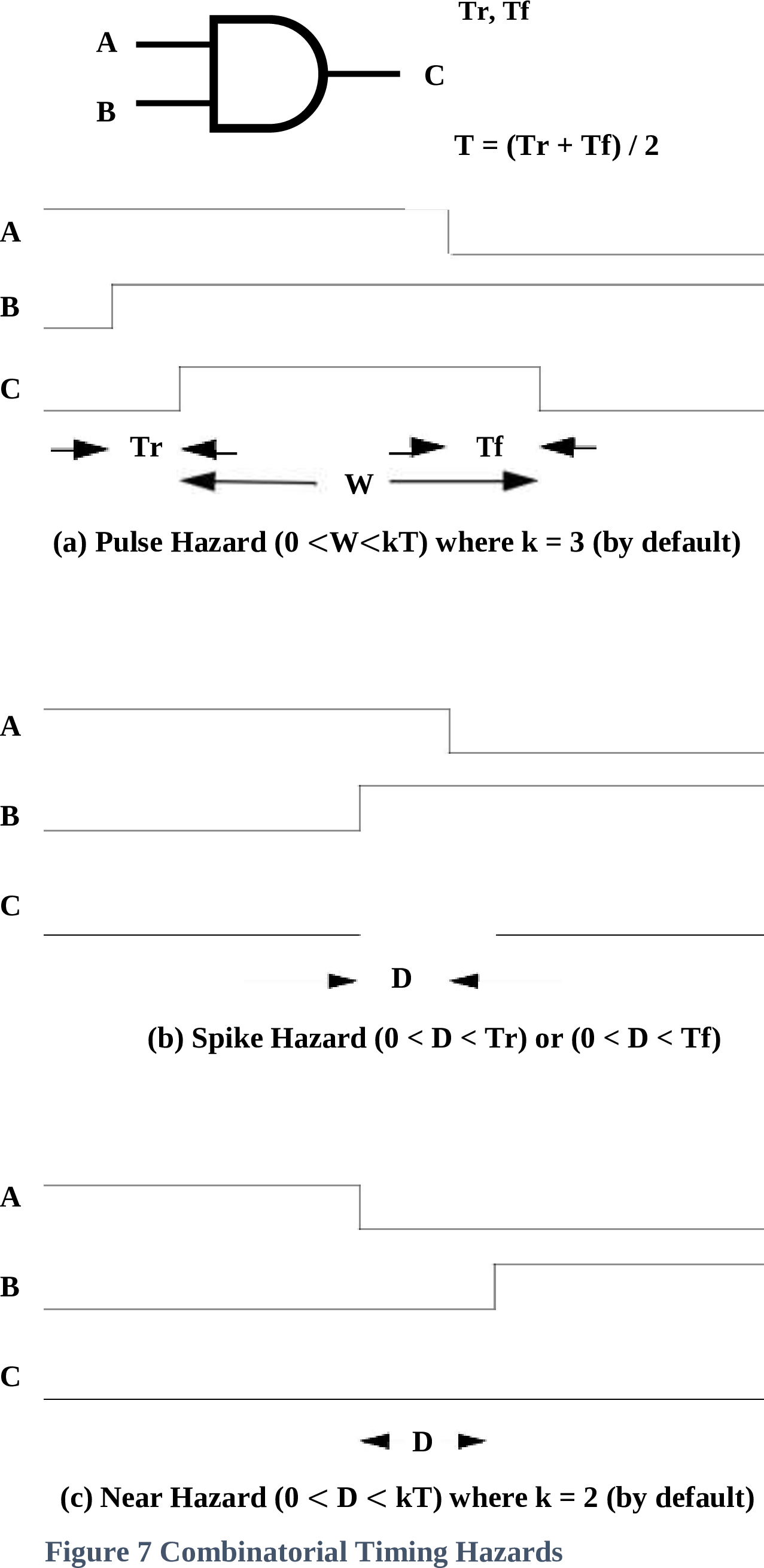
Figure 7 - Combinational Timing Hazards
- (a) Pulse Hazard (0 < W ≤ kT) where k = 3 (by default)
- (b) Spike Hazard
- (c) Near Hazard
Functional Timing Checks
Timing checks are supported for the DNL and DPL (DL) latch and the DNCF, DPCF (DCF), JKNCF (JKCF), JKPCF, TNCF (TCF), and TPCF edge-triggered flip-flops. These checks can be specified within a TIMING-CHECKS block in any PART statement instantiating these built-in primitives.
In the following description, the active clock edge is the clock transition that causes the latch or flip-flop output to change state. This edge is the rising clock transition for the DPL (DL), DPCF (DCF), JKPCF, and TPCF primitives, and the falling clock transition for the DNL, DNCF, JKNCF (JKCF), and TNCF (TCF) primitives.
The supported timing checks are:
- SETUP – this check specifies the minimum duration that an input must be stable prior to an active clock edge:
- DNL, DPL, DNCF, DPCF – setup from D (
SETUP.D) - JKNCF, JKPCF – setup from J (
SETUP.J) and setup from K (SETUP.K) - Additionally, all eight primitives support setup from reset (
SETUP.NR), and setup from set (SETUP.NS). These setup times represent the minimum duration that the reset (set) must be inactive to reliably set (reset) the memory element via clock.
- DNL, DPL, DNCF, DPCF – setup from D (
- HOLD – this check specifies the minimum duration that an input must be stable after an active clock edge:
- DNL, DPL, DNCF, DPCF – hold to D (
HOLD.D) - JKNCF, JKPCF – hold to J (
HOLD.J) and hold to K (HOLD.K) - Additionally, all eight primitives support hold to reset (
HOLD.NR), and hold to set (HOLD.NS)
- DNL, DPL, DNCF, DPCF – hold to D (
- PULSE-WIDTHS – this check specifies the minimum width of a pulse on the set, reset, or clock lines. All eight primitives support: pulse-width reset (
PW.NR), pulse-width set (PW.NS), and high and low pulse-width clock (PW.C.HandPW.C.Lrespectively).
The setup and hold checks for the asynchronous, active-low, set and reset inputs of all eight primitives are associated with the time duration between the rising (trailing) edge of pulses on these inputs and the active clock edge.
Referencing a timing check by itself, without a qualifying pin name or clock level—SETUP, HOLD, PW—specifies all checks of that type. For example, in a TIMING-CHECKS block for a JKCF instance, SETUP specifies all setup checks; SETUP.D, SETUP.J, SETUP.K, SETUP.NR, and SETUP.NS.
Excessive Activity (Oscillation)
Oscillation is defined as excessive activity at a signal in response to a single change of primary input state. In order to determine excessive activity, SIMIC counts the state changes at each signal. When a primary input changes (or a new period starts for timing generators), all counts are reset. By default, oscillation is defined to be 10 transitions at a signal within a single test.
When activity at any signal reaches the defined oscillation limit, SIMIC sets the signal's value to X (unknown). The signal is freed to assume a known value when the next primary input change occurs.
This limit can be redefined globally with the DEFINE command's OSCILLATION (OS) keyword option:
DEFINE OSCILLATION=<count>
where <count> is a number between 2 and 255. To disable oscillation detection, any prefix of the word INFINITE can be used instead of <count>. This option should be exercised with extreme caution, since, if an oscillation does occur, the simulation run will never complete.
Depths and Strengths
SIMIC supports a range of 32,767 gradations of "resistance", called depths, for switch-level components. Depths are assigned to these components with the SERIES-DEPTH (SDEPTH) SNL keyword. Smaller values of depth ("resistance") correspond to greater drive capability.
Since gate-level components can interconnect with switch-level components, it is necessary to establish a correspondence between switch-level depths and gate-level drive strengths. Depths are mapped to strengths as follows:
| Depth | Strength |
|---|---|
| 1 | Power |
| 2 | Driving |
| 3-32,766 | Resistive |
| 32,767 | Floating |
When SIMIC needs to map a strength to a depth value, Resistive strength is mapped to a depth of 3, by default. The default value can be changed with the DEFINE command's RDEPTHS (RD) keyword option:
DEFINE RDEPTH=<n>where <n> is a value between 3 and 32766.
Interval Representation
In order to perform switch-level simulation accurately, SIMIC internally maintains an interval representation for switch-level signal values. The interval contains information on the range of possible values at each signal.
Each interval is represented by a two-tuple of integers whose absolute values range from 1 to 32,767. The integers contain combined depth and level information. If both integers are positive, the level is logical-1. If both integers are negative, the level is a logical-0. Otherwise, the level is an X. The absolute magnitudes of the integers represent depths—the lower the value, the stronger the drive.
Some examples of intervals:
2/2- this represents a driving 1.-3/-3- this represents a resistive 0.2/-2- this represents a driving X.2/20- this represents a logical-1, whose strength is somewhere between 2 and 20.-2/-20- this represents a logical-0, whose strength is somewhere between 2 and 20.32767/-32767- this represents a tristate (Z) condition.
An interval of 2/20, for example, can arise when a node is driven to logical-1 through a depth of 20, and may also be driven to logical-1 through a depth of 2. One situation that can generate this interval is illustrated in Figure 8.
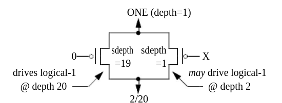
Figure 8 - Sample Situation Generating 2/20 interval
For intervals with unequal components (e.g., 2/20, representing a range of possible depths), SIMIC uses the following simulation output characters:
F- for logical-0.T- for logical-1.U- for X (unknown).
Restricting Simulation Options To A Specified Simulation Interval
Many SIMIC run commands allow restriction of their actions to a specified test and/or time interval. The keyword used to specify this interval is PRANGE (PR). The PRANGE keyword can be attached to the following commands:
BREAKLOOKPRINTTRACEWARNWRITE
Basic Form of PRANGE Keyword
The basic form of the PRANGE keyword is:
PRANGE=[<begin-test>[-<end-test>]] [<begin-time>[-<end-time>]]
where <begin-test> and <end-test> specify the test range, and <begin-time> and <end-time> specify the time range. If omitted, <begin-test> and <begin-time> default to the initial values (test 0, time 0), and <end-test> and <end-time> default to infinity.
Examples:
PRANGE=10       restricts actions to test 10 only
PRANGE=10-20    restricts actions to tests 10 through 20
PRANGE= 5-10    restricts actions to times 5 through 10
PRANGE=5 10-20  restricts actions to test 5, times 10 through 20
Querying Signal and Part Attributes
Overview
Simic has a number of commands that display attributes of signals and parts, such as loading, delay, decay, series-depth, etc. These commands begin with a question mark (?loading, ?delay, ?decay, etc.) and will be covered where appropriate throughout this manual.
Directing Queried Information to a File
All of the query (?) commands output can be sent to a file, with the FILE keyword option. The FILE option is active only for the query command that specifies it. However, if subsequent query commands specify the same file name, then the query output will be appended to that file. If a file exists from a previous session, then that file will be overwritten. The default extension is .qry
Filtering Query Information
The ?delay, ?decay, ?loading, and ?ramp commands can be filtered so that only those values greater or equal to a given threshold will be output. This is accomplished with the BEGIN option. This option is only active for the current query command.
Setting Simulation Breakpoints
Overview
The BREAK (BR) command freezes simulation when specified conditions occur. Once frozen, the state of the circuit can be interrogated with the LOOK and ? commands, the simulation can be resumed, or the session can be terminated.
Multiple BREAK commands can be issued; their effects are cumulative. To cancel a previous BREAK command, use the NO prefix.
Restricting Break To A Specified Interval
Like other SIMIC commands, BREAK supports the PRANGE keyword to restrict breakpoint monitoring to a specific test and/or time interval.
Directing The Destination Of Break Messages
When a breakpoint is encountered, SIMIC outputs a message identifying the condition that caused the break. By default, this message goes to the terminal. Use the FILE (FI) keyword to redirect to a file:
BREAK FILE=<filename> ...Breakpoint At A Specified Signal Transition
Simulation can be stopped when one or more signals undergo a specified transition:
BREAK RISE=<signal-list>    Break on rising transition
BREAK FALL=<signal-list>    Break on falling transition
BREAK CHANGE=<signal-list>  Break on any transition
Breakpoint When A Signal State Becomes Unknown (X)
To break when any signal (or a specified list of signals) becomes unknown:
BREAK X:              Break on any signal going to X
BREAK X=<signal-list>  Break on specified signals going to X
Breakpoint When A Signal Goes To Floating Unknown (Z)
To break when signals enter a high-impedance (floating) state:
BREAK Z:              Break on any signal going to Z
BREAK Z=<signal-list>  Break on specified signals going to Z
Breakpoint At Signal Conflict Hazard
A conflict occurs when multiple drivers attempt to drive a signal to opposing logic levels:
BREAK CONFLICT:              Break on any conflict
BREAK CONFLICT=<signal-list>  Break on conflicts at specified signals
Breakpoint At An Oscillation
To break when oscillation is detected at any signal:
BREAK OSCILLATION:Breakpoint At A Combinational Timing Hazard
SIMIC can break when pulse, spike, or near hazards are detected:
BREAK PULSE:              Break on pulse hazards
BREAK SPIKE:              Break on spike hazards
BREAK MEMSPIKE:           Break on spike hazards at memory elements
BREAK NEAR:               Break on near hazards
Breakpoint At A Functional Timing Violation
To break when setup, hold, or pulse-width violations occur:
BREAK SETUP:    Break on setup violations
BREAK HOLD:     Break on hold violations
BREAK PW:       Break on pulse-width violations
Breakpoint On Input Change While The Circuit Is Unstable
To detect when primary inputs change before the circuit has stabilized:
BREAK UNSTABLE:Breakpoint At Specified Intervals
SIMIC can break at regular test or time intervals:
BREAK PSTEP=<n>    Break every n tests
BREAK TSTEP=<n>    Break every n time units
Breakpoint On Multi-Signal Pattern Matching
One of the most powerful troubleshooting features is the ability to break when multiple signals simultaneously match a specific pattern. This is invaluable for:
- Detecting specific circuit states (e.g., "break when counter equals 42")
- Finding when a bus reaches a particular value
- Debugging state machine transitions
- Isolating problems that only occur under specific signal combinations
Basic Usage
BREAK PATTERN=<pattern> LIST=<signal-list>
The pattern string consists of: 0 (logic 0), 1 (logic 1), X (unknown), Z (high-impedance), and ? (wildcard - matches any value).
Common Troubleshooting Scenarios
Binary Pattern with Wildcards
Break when specific control signals are set, regardless of data signals:
BREAK PATTERN=1?00 LIST=CLK,DATA,STATUS,ENABLEThis breaks when CLK=1, STATUS=0, and ENABLE=0, regardless of DATA's value.
Hexadecimal Bus Values
Break when a data bus reaches a specific hex value:
BREAK PATTERN=#FF LIST=DATA[7:0]    Break when bus = 0xFF
BREAK PATTERN=#A5 LIST=ADDR[7:0]    Break when address = 0xA5
Integer Counter Values
Break when a counter reaches a particular decimal value:
BREAK PATTERN=%100 LIST=COUNTER[7:0]    Break when counter = 100
BREAK PATTERN=%-5 LIST=COUNTER[7:0]     Break when counter = -5
State Machine Debugging
Combine with PRANGE to break on a state only in a specific test range:
BREAK PATTERN=1010 LIST=STATE[3:0] PRANGE=50-100Pattern Format Options
Patterns support multiple radix formats:
- Binary:
0101or^0101(default) - Hexadecimal:
#A5(signal count must be divisible by 4) - Octal:
*752(signal count must be divisible by 3) - Integer:
%42(2's complement),1%-5(1's complement),u%100(unsigned)
Troubleshooting Tips
? symbol to focus on specific signals while ignoring others. For example, PATTERN=1??0 only cares about the first and last signals in a 4-signal list.
TRACE to see exactly what led to the matched condition. Set up the trace first, then let simulation run until the pattern matches.
To clear a pattern breakpoint:
NO BREAK PATTERN:Breakpoint on Strobe Error
When using strobe checking features, break on mismatches:
BREAK STROBE:Setting Simulation Warnings (Watchpoints)
Overview
The WARN (WA) command is similar to the BREAK command, except that simulation continues after the warning message is issued. The WARN command supports the same condition keywords as BREAK:
WARN RISE=<signal-list>
WARN FALL=<signal-list>
WARN CHANGE=<signal-list>
WARN X:
WARN Z:
WARN CONFLICT:
WARN OSCILLATION:
WARN PULSE:
WARN SPIKE:
WARN MEMSPIKE:
WARN NEAR:
WARN SETUP:
WARN HOLD:
WARN PW:
WARN UNSTABLE:
WARN STROBE:
Suppressing Excessive Messages on a Per-Signal Basis
To prevent flooding of warning messages for frequently triggering signals, SIMIC allows limiting the number of warnings per signal:
WARN LIMIT=<n>
where <n> is the maximum number of warnings to issue for each signal. After this limit is reached, no further warnings are issued for that signal.
Warning Defaults
By default, SIMIC issues warnings for:
- Spike hazards (at all nodes)
- Functional timing violations
To disable default warnings:
NO WARN:Tracing Circuit Activity
Overview
The TRACE (TR) command monitors and reports activity at specified signals during simulation. When a traced signal changes value, SIMIC outputs a message showing:
- Current simulation time and test number
- Signal name
- Old and new values
- Causality information (if requested)
Basic usage:
TRACE LIST=<signal-list>Restricting Trace to a Specified Interval
Use the PRANGE keyword to limit tracing to specific tests and/or times:
TRACE LIST=<signal-list> PRANGE=10-20 5-100Directing the Destination of Trace Output
By default, trace output goes to the terminal. To redirect to a file:
TRACE LIST=<signal-list> FILE=<filename>Specifying Signals to Trace
The LIST (LI) keyword specifies which signals to trace. Several special keywords are available:
LIST:- Trace all signalsINPUTS:- Trace all primary inputsOUTPUTS:- Trace all primary outputsBUSES:- Trace all bus signals
Requesting Causality Information
The EXPAND (EX) keyword requests that SIMIC report why a signal changed:
TRACE LIST=<signal-list> EXPAND:
When EXPAND is specified, SIMIC traces back through the circuit to identify which input changes caused the traced signal to transition.
Using Trace to Locate Critical Paths
By analyzing trace output with EXPAND, you can identify the longest paths through your circuit—useful for timing optimization. The causality chain shows the sequence of gates from input to output, with the cumulative delay.
Probing For Signal State Information
Overview
The value of any signal in the circuit may be interrogated with the LOOK (LO) run command at any breakpoint in the simulation. The LIST (LI) keyword option is used to specify the signals. The format of this command is:
LOOK LIST=<list of signals>
where <list of signals> is a list of signals whose values are requested. Note that SIMIC generates a time/test stamp, and for each requested signal, outputs:
- The signal's name.
- The signal's value in SIMIC character format. If the driving device requires depths (switches, tristating elements, wire-ties, etc.), then the value's interval representation will also be displayed (in parenthesis).
- The signal's driver. This can be either a built-in or user-defined primitive, a primary input (or bus), or a global constant (logical-0, logical-1, Tristate (Z)).
The LOOK command's LIST keyword option is not sticky; SIMIC only reports the values of signals currently specified with the LIST keyword.
Displaying Topology As Well As Values
Very often, it is useful to be able to trace the source of an incorrect signal value. This process can be simplified by including some topological information in the LOOK output. The INPUTS (IN) keyword option controls reporting of element input values. To add fanin (element input value) information to the LOOK output, issue the command:
LOOK INPUTS:To remove fanin information from the LOOK output:
NO LOOK INPUTS:
Once enabled, each subsequent LOOK LIST command will then contain information about the fanin values. For each input of the element generating the traced signal, this information consists of (1) the name of the signal connected to the input and (2) the input signal's value.
Fanout information can also be included in the LOOK LIST output with the OUTPUTS (OU) keyword option:
LOOK OUTPUTS:
Once enabled, each subsequent LOOK LIST command will then contain the instance names of all parts driven by the traced signal.
Fanout information can be subsequently removed from LOOK output with the command:
NO LOOK OUTPUTS:Displaying transition information
To make it easier to trace causality for a change the EXPAND: option will display the previous value and the time of the transition.
Displaying All Signal States
The command:
LOOK LIST:causes SIMIC to generate a table of all signals states (in alphanumeric sequence). The format of this table is equivalent to the PRINT (or WRITE) dump format.
Displaying All Signals At A Specified State
Many times it is useful to see if there are any signals at an 'X' or 'Z' state.
To display all signals at an 'X' state, use the command:
LOOK X:
Similarly, to display all signals at a 'Z' (tristate) value, use the HIZ (HI) keyword option:
LOOK HIZ:
The format of both reports is identical to the LOOK LIST= command's report format. These two commands do not honor the INPUTS: or OUTPUTS: keyword options, if in effect.
Forcing Signal States
Overview
SIMIC allows interactive modification of any signal's state by one of two methods, SET (SE) and CLAMP (CL). They differ only in the length of time that a signal value is forced. The SET value is maintained for a single test, after which the SET signal is freed to assume a consistent value (if the signal is an element output, its state must be consistent with the element's input state). A CLAMPed value, however, will remain at the forced value from the specified test onwards, until explicitly freed with the NO CLAMP command.
Specifying Force Values and Tests
The value to force is selected by the keyword options: ONE (ON), ZERO (ZE), X, and HIZ (HI), for Logical-1, Logical-0, Unknown, and Tristate, respectively. The format is:
SET <value-option>=<list of signals>or
CLAMP <value-option>=<list of signals>
where <value-option> is the appropriate keyword option, as described above.
These values will be applied at the start of the next test, after resumption of simulation. Signals that are SET will only remain forced for that test, but signals that are CLAMPed will remain forced until explicitly released with the NO CLAMP command, or CLAMPed to another value.
If values must be forced farther in the future than the next test, the TNUM (TN) keyword option of the SET or CLAMP run command can be used to specify the appropriate test. If the TNUM keyword is not specified, then the SET or CLAMP will be applied at the start of the next test. The form of the TNUM keyword option is:
SET TNUM=<n>or
CLAMP TNUM=<n-m>
where <n> is the test number in which a value is to be SET or CLAMPed and <m> is the release the CLAMP. If <m> is omitted, then the CLAMP is not released, if both <m> and the hyphen are omitted, then the clamp is only active for the single test <n>. Multiple test ranges for the CLAMP command must be specified in subsequent CLAMP commands.
The TNUM keyword option is not sticky, and if specified, must be included within the same command as the value assignments.
If conflicting values are simultaneously specified for the same signal in SET and CLAMP commands, then the CLAMP command overrides the SET.
If a built-in flip-flop primitive's output is SET or CLAMPED, the master rank is also assigned the SET or CLAMPED value.
Modifying Delay Parameters
SIMIC allows interactive modification of gate and path delays during simulation, which is useful for:
- Performing "what-if" timing analysis
- Debugging timing-related failures
- Simulating process variations
Delay modifications are made using the CHANGE keyword in the SET or CLAMP commands:
SET CHANGE=<percent> LIST=<signal-or-part-list>
where <percent> is the percentage change (e.g., 150 for 50% increase, 50 for 50% decrease).
Example:
SET CHANGE=120 LIST=u1.and1    Increase delay by 20%
SET CHANGE=80 LIST=clk_path    Decrease delay by 20%
Enabling And Disabling X-Propagation
The XPROPAGATE (XP) command controls how unknown (X) values propagate through the circuit in response to hazards. This is particularly important for spike and near hazard handling.
Spike Hazards
By default, SIMIC propagates an X-pulse when a spike hazard is detected. To filter spikes instead:
XPROPAGATE SPIKE=FILTER
XPROPAGATE SPIKE=PROPAGATE     (restore default)
Near Hazards
Similarly, near hazard X-propagation can be controlled:
XPROPAGATE NEAR=FILTER
XPROPAGATE NEAR=PROPAGATE
Functional Timing Violations
X-propagation for setup, hold, and pulse-width violations:
XPROPAGATE SETUP=FILTER
XPROPAGATE HOLD=FILTER
XPROPAGATE PW=FILTER
Querying and Modifying Spike Control Parameters
Querying Spike Control Parameters
To display current pulse and near hazard window settings:
? PULSE:
? NEAR:
Modifying Spike Control Parameters
The pulse hazard window can be modified during simulation:
DEFINE PULSE=<k>
where <k> is the multiplier of average gate delay. Similarly for near hazards:
DEFINE NEAR=<k>Querying and Modifying Functional Timing Check Parameters
Querying Functional Timing Check Settings
To display current timing check parameters for specific parts:
? CHECKS LIST=<part-list>This displays all timing check parameters (setup, hold, and pulse-width) for the specified flip-flops or latches.
Example:
? CHECKS LIST=u1.ff1,u2.latch1Modifying Functional Timing Check Parameters
Timing check parameters can be modified in two ways:
Setting Timing Check Parameters To Absolute Values
SET SETUP=<value> LIST=<part-list>
SET HOLD=<value> LIST=<part-list>
SET PW=<value> LIST=<part-list>
Setting Timing Check Parameters Relative To Current Values
SET SETUP=<percent> LIST=<part-list> CHANGE:
SET HOLD=<percent> LIST=<part-list> CHANGE:
where <percent> is the percentage of the current value (e.g., 150 for 50% increase).
Modifying Drive Values
The drive strength of signals can be modified using the DRIVE keyword:
SET DRIVE=<strength> LIST=<signal-list>
where <strength> is one of:
POWERDRIVINGRESISTIVEFLOATING
Replaying Portions of the Simulation
Description
SIMIC supports checkpointing and restoration, allowing you to save the circuit state at a specific point and later return to that state. This is particularly useful for:
- Debugging specific test cases repeatedly
- Trying different "what-if" scenarios from the same starting point
- Avoiding re-simulation of long initialization sequences
Creating The Checkpoint File
To save the current circuit state:
SAVE FILE=<filename>or to use the default checkpoint filename:
SAVE FILE:Restoring the Saved State's Time and Test
To restore a previously saved state:
RESTORE FILE=<filename>or:
RESTORE FILE:After restoring, simulation continues from the saved test and time, with all signal values and circuit state restored to their checkpointed values.
To restore and immediately continue to a specific test:
RESTORE FILE: TNUM=<test-number>Summary of Debugging Commands
This chapter covered SIMIC's comprehensive suite of interactive debugging tools:
- BREAK - Set breakpoints on conditions
- WARN - Set watchpoints that don't stop simulation
- TRACE - Monitor signal activity with causality analysis
- LOOK - Probe circuit state and topology
- SET/CLAMP - Force signal values
- ? - Query part and signal attributes
- PRANGE - Restrict commands to specific intervals
- XPROPAGATE - Control X-propagation behavior
- SAVE/RESTORE - Checkpoint and replay simulation
These commands can be combined to create powerful debugging workflows tailored to specific design verification challenges.